Metal Bellows Couplings Servo-Insert Couplings Line Shafts
|
|
|
- Regina Crawford
- 5 years ago
- Views:
Transcription


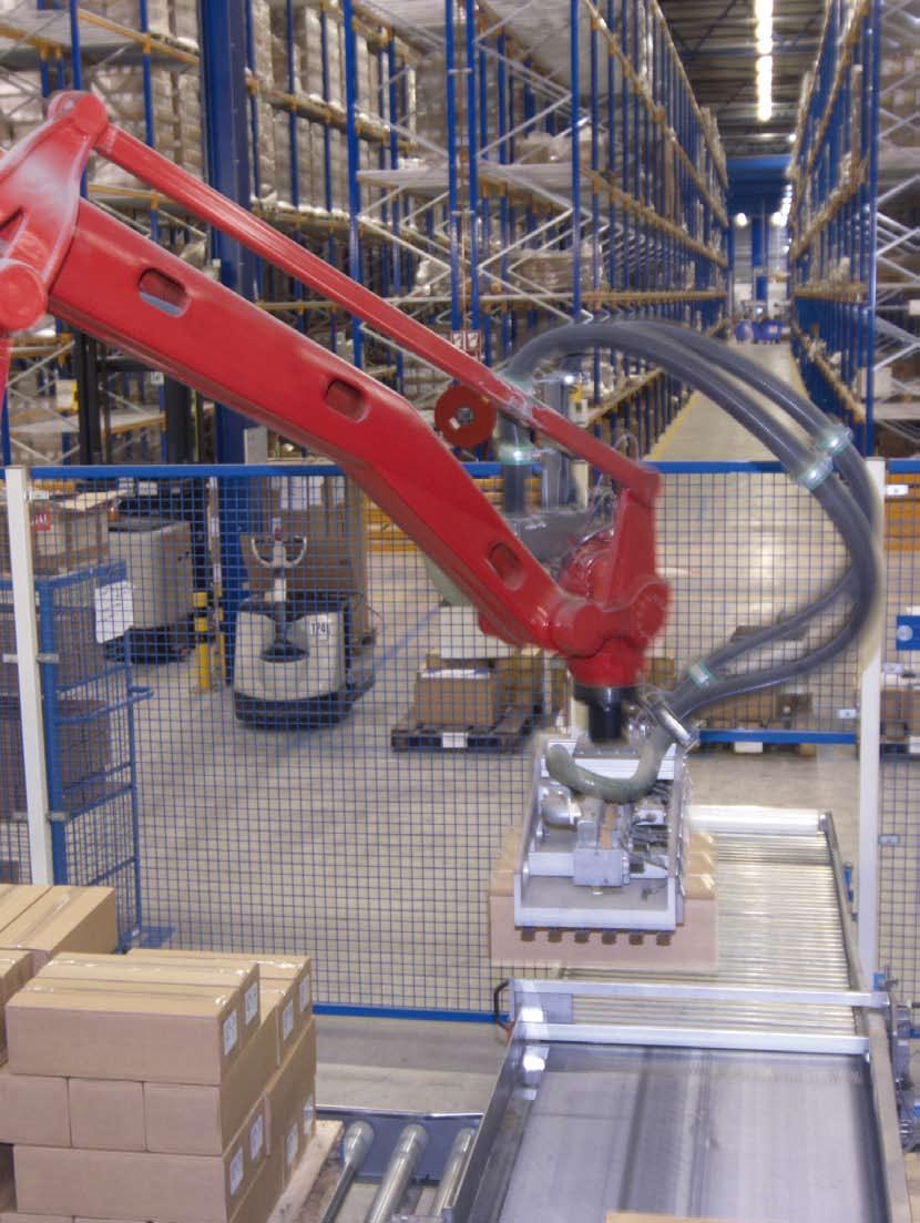
1 US Metal Bellows Couplings Servo-Insert Couplings Line Shafts Partner for performance


2 A Global Presence For You The RINGFEDER POWER TRANSMISSION GMBH was founded in 1922 in Krefeld, Germany to fabricate and promote Friction Spring technology. Today we have expanded our offerings to top power transmission and damping products. Innovative thinking sets us apart and allows us to develop progressive and economical solutions to support our customers. 2


")

3 Special applications require special solutions Our extensive range of RINGFEDER POWER TRANSMISSION products can be applied to solve most applications. We don t just sell, but by understanding the individual requirements of our customers (e.g. loads on the components, easy installation/removal capability and reduction of production costs) assist you in every step with innovative engineering to plan efficient and technically mature solutions. 3


4 Overview Metal Bellows Couplings Servo-Insert Couplings Line Shafts 4
5 Content 02 Pages Corporate Image Line Shafts 04 Overview 05 Content Metal Bellows Couplings 06 Basics 11 Product Overview 12 EKN 14 DKN 16 DKN/S 18 PKN 20 AKN 22 AKD 24 AK 26 CKN 45 Basics 47 Product Overview 48 ADS-ZW 50 ADS/B-ZW 52 ASS/A-ZW 54 ASS/B-ZW 56 ADS/H-ZW 58 AKN-ZW Mounting Instructions 60 Metal Bellows Couplings 62 Servo-Insert Couplings 66 Line-Shafts Servo-Insert Couplings 28 Basics 31 Product Overview 32 EK/GS 34 DK/GS 36 ADS 38 ADS/R 40 ASS/A 42 Technical Information 44 Preview: ICL & SMC Fax Inquiry 68 Fax Inquiry Couplings 69 Fax Inquiry Line Shafts 71 Delivery Program RINGFEDER POWER TRANSMISSION All technical details and information are non-binding and cannot be used as a basis for legal claims. The user is obligated to determine whether the represented products meet his requirements. We reserve the right at all times to carry out modifications in the interests of technical progress. Upon the issue of this catalogue all previous brochures and questionnaires on the products displayed are no longer valid. 5

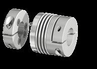
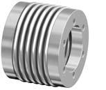
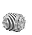
6 Metal Bellows Couplings Basics Backlash-free Metal Bellows Couplings Characteristics of Metal Bellows Couplings: Backlash-free transmission of torque High torsional stiffness, precision of transmission of rotational angle Different torsional stiffness Backlash-free shaft connection Metal bellows made of stainless steel Simple and safe assembly Compensation of radial, axial and angular misalignment Free of wear, maintenance-free, no downtimes Not sensitive to temperatures between -22 F and 212 F Nominal torques between lb-in 6

7 Metal Bellows Couplings Basics Backlash-free Metal Bellows Couplings are used in applications where maintaining torsional rigidity between two shafts is critical. Pumps with axial and vertical drives High dynamic portal drives Spindle lifting units Linear units Packaging machines Machine tools Special machines 7
8 Technical Information Metal Bellows Couplings Design / Sample Calculation Coupling Design/ General information Backlash-free torsionally stiff Metal Bellows Couplings are installation ready when delivered. The metal bellows are made of stainless steel, other parts are made of aluminum or steel with some parts having an environmentally friendly protective coating. Bores are supplied with the ISO H7 tolerance standard, and we recommend that shafts have the g6 transition fit tolerance. Please see the chart below for conversion to the ANSI standard. The backlash for other fits may not exceed Torque is generated between the coupling hub and the shaft by compression and friction on the contact surfaces. Special attention should be given to the correct tightening torque on the clamp screws as well as the condition of the shaft and hub bore surfaces. The contact surfaces must be free of oil and grease and the shaft must have a surface roughness RMS 63. Keyways can also be supplied upon request to metric or imperial standards. Torque capacities published are based on strictly following our guidelines. Coupling Selection Metal Bellows couplings are generally selected based on nominal torque needed for the application, Tkn in our tables. The nominal torque must always be higher than the running torque. This generally applies for applications involving servo motors whose acceleration torque in both forward and reverse directions exceed the nominal torque. For applications involving controlled, highly dynamic drives, the following safety factors have proven to be reliable in practice: K= 1.5 for steady torques K=2.0 for intermittent torques K=2.5-4 for oscillating torques For servo drives in machine tools: k= We would be pleased to design your metal bellows coupling for you. Feel free to use our experience and know-how for your success. Give us a call! T KN K x T AS x J Mach J Mtr x J Mach = [lb-in] Servo drive Sliding carriage Metal Bellows Coupling Ball bearing spindle 8

9 Technical Information Metal Bellows Couplings Design in consideration of dynamic torsional stiffness Although metal bellows couplings are backlash-free and torsionally rigid, keep in mind that the coupling links two rotating masses. In adverse cases the coupling can act like a torsion spring with high stiffness. The regulating oscillation of the drives and the harmonic oscillation in the armature current of the motor therefore must never be within the range of the mechanical resonance frequency. In practice the resonance frequency f res must be twice as high as the excitation frequency of the drive. The dynamic torsional stiffness C Tdyn was selected so that it would not be within the range of parasitic oscillation of most applications. Various levels of torsional stiffness are available as standard versions. We would be pleased to design your metal bellows couplings for you. Feel free to use our experience and know-how for your success. Give us a call! Calculation for the application of a metal bellows coupling in a machine tool drive Drive related data for servo motor/ft 5104: Peak torque T AS = 1416 lb-in Moment of inertia J Mtr = 16.2 x 10⁻² lb-in-s 2 The low moment of inertia for the metal bellows coupling is disregarded. K = Load factor, impulse factor selected for this drive K = 2; Output data for Moment of inertia of ball screw and machine tool: slide: J Mach = 15 x 10-2 lb-in-s 2 f res = 1 2π C Tdyn x J Mtr + J Mach J Mtr x J Mach = [Hz] Design according to torque: Coupling selection: AKD 200, T KN = 1770 lb-in, C Tdyn = 1027 x 103 lb-in/rad The metal bellows coupling is selected sufficiently, since 1770 lb-in > 1363 lb-in T KN K x T AS x J Mach J Mtr + J Mach = 2 x 1416 lb-in x 15 x 10-2 lb-in-s 2 ( ) x 10-2 lb-in-s 2 = 1363 lb-in Design according to the resonance frequency: The arithmetic calculation is clearly higher than the expected resonance frequency f res = 1 2π C Tdyn x J Mtr + J Mach J Mtr x J Mach = 1 2π x lb-in/rad x lb-in-s x 0.15 lb-in-s 2 = 580 Hz 9
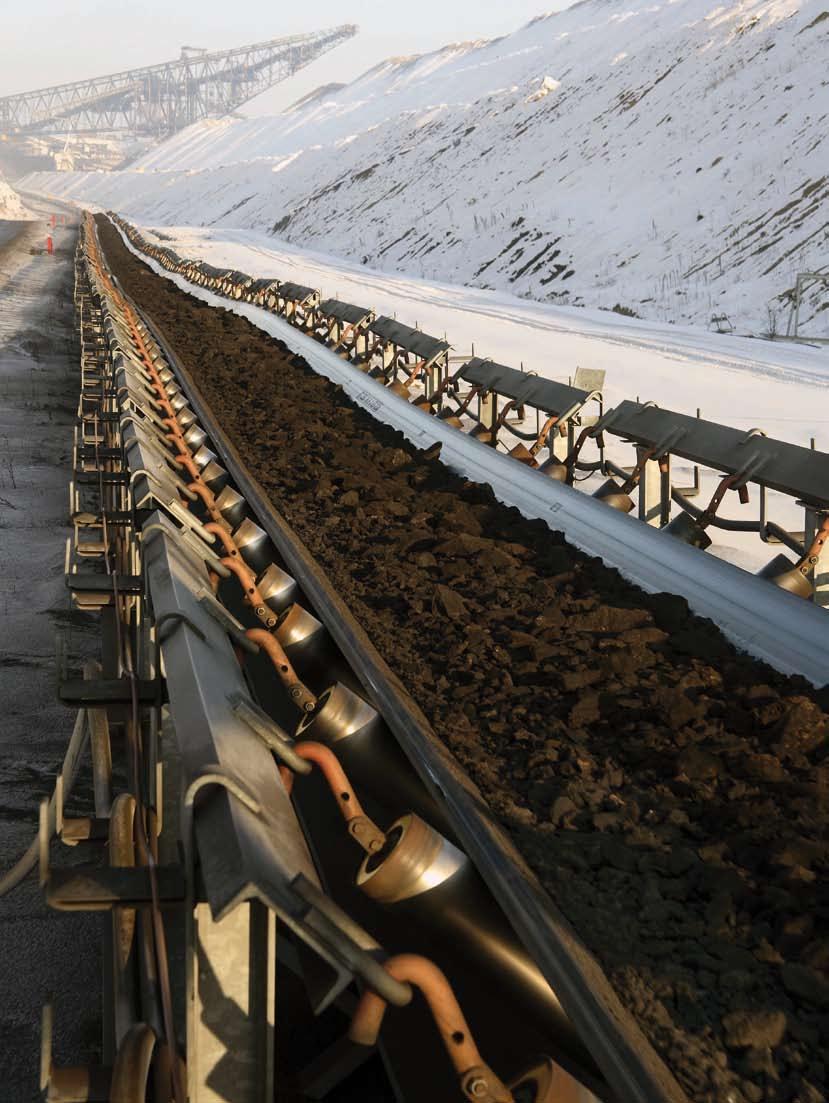
10 Conveyor


11 Overview Metal Bellows Couplings EKN DKN DKN /S PKN Metal Bellows Coupling with radial set-screws Metal Bellows Coupling with clamping hubs Metal Bellows Coupling with clamping hubs and expanding clamps Metal Bellows Coupling with detachable clamping hub for easier assembly Page 12 Page 14 Page 16 Page 18 AKN AKD AK CKN Metal Bellows Coupling with clamping hubs and short length Metal Bellows Coupling with clamping hubs Metal Bellows Coupling with integral keyless locking device Metal Bellows Coupling with adaptor flange Page 20 Page 22 Page 24 Page 26 11

12 Backlash-free Metal Bellows Coupling EKN øa = Outer diameter ød 1 H7 = Bore diameter ød 2 H7 = Bore diameter C = Guided length shaft bore G = Camping screws I = Clamping screw centerline L = Total length C 1 = Bore tolerance for D 1 C 2 = Bore tolerance for D 2 Size L Ø A Ø D1 H7 C1 Ø D2 H7 C2 C I G ±0.079 Inch mm /0.91/ M /0.98/ M / xM /1.26/ xM / xM / xM6 Moment of inertia and weight (mass) are calculated with reference to the largest bore size. Example: EKN Size Length Ø D1 Ø D2 Further details* EKN 20/ XX 12
13 Ø D1 H7 L Ø D2 H7 Ø A 120 Technical Data T KN = Nominal torque C t = Dynamic torsional stiffness Kr = Max. approved misalignment radial Ka = Max. approved misalignment axial Kw = Max. approved misalignment angular J = Moment of inertia M A = Tightening torque of screws n max = Max. rotational speed I C G ISO 4029 (DIN 916) Sectional view Technical Data Size T KN M A C t n max Ka Kw Kr Weight J lb-in 10 3 lb-in/rad rpm ± Inch Degrees Inch lbs 10-3 lb-in /1682/ /0.012/ /2/ /0.006/ /3364/ /0.012/ /2/ /0.006/ /0.015/ /0.79/ / / / / / / /11507/ /0.016/ /2/ /0.008/ /0.053/ /5.47/ / / / / / / / / / / / /75.2 Fittings: Hubs: Standard fit H7 Keyways: Standard fit JS9 Materials: Hubs made of aluminium Metal bellows made of stainless steel Special designs : Coupling completely made of stainless steel (on request) Keyway acc. to DIN or ANSI B
14 Backlash-free Metal Bellows Coupling DKN øa = Outer diameter ød1 H7 = Bore diameter ød2 H7 = Bore diameter øh = Clearance diameter C = Guided length shaft bore G = Clamping screws I = Radius to clamp screw K = Radius to clamp screw L = Total length C 1 = Bore tolerance for D 1 C 2 = Bore tolerance for D 2 Size L Ø A Ø H Ø D1 H7 C1 Ø D2 H7 C2 C K I G ±0.079 Inch mm /0.94/ M /1.02/ M / M /1.50/ M / M / M4 Moment of inertia and weight (mass) are calculated with reference to the largest bore size. Example: DKN Size Length Ø D1 Ø D2 Further details* DKN 20/ XX 14
15 Ø D1 H7 I L G ISO 4762 (DIN 912) Ø D2 H7 Ø A Ø H K Technical Data T KN = Nominal torque C t = Dynamic torsional stiffness Kr = Max. approved misalignment radial Ka = Max. approved misalignment axial Kw = Max. approved misalignment angular J = Moment of inertia M A = Tightening torque of screws n max = Max. rotational speed C Sectional view Technical Data Size T KN M A C t n max Ka Kw Kr Weight J lb-in 103 lb-in/rad rpm ± Inch Degrees Inch lbs 10-3 lb-in /1682/ /0.012/ /2/ /0.006/ /3364/ /0.012/ /2/ /0.006/ /22/ /0.99/ / / / / / / /11507/ /0.016/ /2/ /0.008/ /84/ /9.23/ / / / / / / / / / / /287 79/85 Fittings: Hubs: Standard fit H7 Keyways: Standard fit JS9 Materials: Hubs made of aluminium Metal bellows made of stainless steel s Special designs : Coupling completely made of stainless steel (on request) Keyway acc. to DIN or ANSI B
16 Backlash-free Metal Bellows Coupling DKN/S øa = Outer diameter ød1 H7 = Bore diameter ød2 f7 = Clamp diameter øh = Clearance diameter C = Guided length shaft bore G = Clamping screws G1 = Clamping screw I = Radius to clamp screw J = Clamp length K = Radius to clamp screw L ± 0.08 = Total length C 1 = Bore tolerance for D 1 C 2 = Bore tolerance for D 2 Size L C J Ø A Ø H Ø D1 H7 C1 Ø D2 H7 C2 K I G G1 ±0.079 Inch mm /1.22/ M2 M /1.30/ M2 M / M2.5 M /1.85/ M3 M / M4 M / M4 M6 Moment of inertia and weight (mass) are calculated with reference to the largest bore size. Example: DKN/S Size Length Ø D1 Further details* DKN/S 20/ XX In this version, the expandable adaptor shaft, (length J and diameter D2) can be expanded to clamp internally inside the mating component. Simply by tightening the socket head cap screw G1 the expandable sleeve clamps inside the component, thereby transmitting torque backlash-free from one shaft to the other. 16
17 Technical Data Ø A Ø D1 H7 I L J G ISO 4762 (DIN 912) Ø D2 f7 Ø H K T KN = Nominal torque C t = Dynamic torsional stiffness Kr = Max. approved misalignment radial Ka = Max. approved misalignment axial Kw = Max. approved misalignment angular J = Moment of inertia M A = Tightening torque of screws n max = Max. rotational speed C G1 ISO 4762 (DIN 912) Sectional view Technical Data Size T KN M A C t n max Ka Kw Kr Weight J lb-in 10 3 lb-in/rad rpm ± Inch Degrees Inch lbs 10-3 lb-in /1682/ /0.012/ /2/ /0.006/ /3364/ /0.012/ /2/ /0.006/ /29/ / / / / / / /11507/ /0.016/ /2/ /0.008/ /90/ /7.86/ / / / / / / / / / / / /87.49 Fittings: Hubs: Standard fit H7 Expanding Clamps: Standard fit f7 Keyways: Standard fit JS9 Materials: Hubs made of aluminium Metal bellows made of stainless steel Special designs: Coupling completely made of stainless steel (on request) Keyway acc. to DIN or ANSI B

18 Backlash-free Metal Bellows Coupling PKN øa = Outer diameter ød1 H7 = Bore diameter ød2 H7 = Bore diameter øh = Clearance diameter C = Guided length shaft bore G = Clamping screws I = Radius to clamp screw K = Radius to clamp screw L ± 0.08 = Total length N = Basic dimension C 1 = Bore tolerance for D 1 C 2 = Bore tolerance for D 2 Size L N Ø A Ø H Ø D1 H7 C1 Ø D2 H7 C2 C K I G ±0.079 Inch mm / / M / / M / / M / / M / / M / / M / / M / / M10 Moment of inertia and weight (mass) are calculated with reference to the largest bore size. Example: PKN Size Ø D1 Ø D2 Further details* PKN XX One split clamping hub can be separated from the coupling for easier assembly such as when two components need to be connected in a blind hole. Simply mount one side of the coupling on one shaft and the other side of the couple on the opposite shaft and slide them together. 18
19 Ø D1 H7 I L-1 N N/2 N/2 Ø D2 H7 Ø A G ISO 4762 (DIN 912) Ø H K Technical Data T KN = Nominal torque C t = Dynamic torsional stiffness Kr = Max. approved misalignment radial Ka = Max. approved misalignment axial Kw = Max. approved misalignment angular J = Moment of inertia M A = Tightening torque of screws n max = Max. rotational speed C Sectional view Technical Data Size T KN M A C t n max Ka Kw Kr Weight J lb-in 10 3 lb-in/rad rpm ± Inch Degrees Inch lbs 10-3 lb-in Fittings: Hubs: Standard fit H7 Keyways: Standard fit JS9 Materials: Hubs made of aluminium Metal bellows made of stainless steel Special designs : Coupling completely made of stainless steel (on request) Keyway acc. to DIN
20 Backlash-free Metal Bellows Coupling AKN øa = Outer diameter ød1 H7 = Bore diameter ød2 H7 = Bore diameter øh = Clearance diameter C = Guided length shaft bore G = Clamping screws I = Radius to clamp screw K = Radius to clamp screw L ± 0.08 = Total length C 1 = Bore tolerance for D 1 C 2 = Bore tolerance for D 2 Size L Ø A Ø H Ø D1 H7 C1 Ø D2 H7 C2 C K I G T KN ±0.079 Inch lb-in M M M M M M M M Moment of inertia and weight (mass) are calculated with reference to the largest bore size. Example: AKN Size Length Ø D1 Ø D2 Further details* AKN XX 20
21 Ø D1 H7 I L K G ISO 4762 (DIN 912) Ø D2 H7 Ø A Ø H Technical Data T KN = Nominal torque C t = Dynamic torsional stiffness Cr = Radial spring stiffness Ca = Axial spring stiffness Kr = Max. approved misalignment radial Ka = Max. approved misalignment axial Kw = Max. approved misalignment angular J = Moment of inertia M A = Tightening torque of screws n max = Max. rotational speed C Sectional view Technical Data Size M A C t Cr Ca n max Ka Kw Kr Weight J lb-in 10 3 lb-in/rad 10 3 lb-in/rad rpm ± Inch Degrees Inch lbs lb-in Fittings: Hubs: Standard fit H7 Keyways: Standard fit JS9 Materials: Hubs made of aluminium Metal bellows made of stainless steel Special designs : Coupling completely made of stainless steel (on request) Keyway acc. to DIN
22 Backlash-free Metal Bellows Coupling AKD øa = Outer diameter total coupling ød1 H7 = Bore diameter ød2 H7 = Bore diameter øh = Clearance diameter C = Guided length shaft bore G = Clamping screws I = Radius to clamp screw K = Radius to clamp screw L ± 0.08 = Total length C 1 = Bore tolerance for D 1 C 2 = Bore tolerance for D 2 Size L Ø A Ø H Ø D1 H7 C1 Ø D2 H7 C2 C K I G ±0.079 Inch M M M M M M M M14 Moment of inertia and weight (mass) are calculated with reference to the largest bore size. Example: AKD Size Ø D1 Ø D2 Further details* AKD XX 22
23 Ø D1 H7 I C L K G ISO 4762 (DIN 912) Ø D2 H7 Ø A Ø H Technical Data T KN = Nominal torque C t = Dynamic torsional stiffness Cr = Radial spring stiffness Ca = Axial spring stiffness Kr = Max. approved misalignment radial Ka = Max. approved misalignment axial Kw = Max. approved misalignment angular J = Moment of inertia M A = Tightening torque of screws n max = Max. rotational speed Sectional view Technical Data Size T KN M A C t Cr Ca n max Ka Kw Kr Weight J lb-in 10 3 lb-in/rad 10 3 lb-in/rad rpm ± Inch Degrees Inch lbs lb-in Fittings: Hubs: Standard fit H7 Keyways: Standard fit JS9 Materials: Hubs made of aluminium Metal bellows made of stainless steel Special designs: Coupling completely made of stainless steel (on request) Keyway acc. to DIN
24 Backlash-free Metal Bellows Coupling AK øa = Outer diameter total coupling øb = Outer diameter Hub ød1 H7 = Bore diameter ød2 H7 = Bore diameter øt = Pitch circle diameter E = Overall length - relaxed condiotion G = Screws J = Coupling Body length - relaxed condition L ± 0.08 = Total length C 1 = Bore tolerance for D 1 C 2 = Bore tolerance for D 2 Size L Ø A ØB Ø T Ø D1 H7 Ø D2 H7 E J G ±0.079 Inch mm / / / /1.50 6xM / / / /1.81 6xM / / / /2.40 6xM / / / /2.40 6xM / / / /2.48 6xM / / / /2.64 6xM / / / /2.83 6xM / xM / xM xM / xM16 Moment of inertia and weight (mass) are calculated with reference to the largest bore size. Example: AK Size Length Ø D1 Ø D2 Further details* AK 150/ XX 24
25 L Technical Data T KN = Nominal torque C t = Dynamic torsional stiffness Cr = Radial spring stiffness Ca = Axial spring stiffness Ø A Ø T Ø D1 H7 J Ø D2 H7 Ø B G ISO 4017 (DIN 933) Kr = Max. approved misalignment radial Ka = Max. approved misalignment axial Kw = Max. approved misalignment angular J = Moment of inertia M A = Tightening torque of screws n max = Max. rotational speed E Sectional view Technical Data Size T KN M A C t Cr Ca n max Ka Kw Kr Weight J lb-in 10 3 lb-in/rad 10 3 lb-in/rad rpm ± Inch Degrees Imch lbs lb-in / / / / / / / / / / / / / / / / / / / / / / / / / / / / / / / / / / / / / / / / / / Fittings: Hubs: Standard fit H7 Materials: Hubs made of aluminium (Size ) Hubs made of steel (Size ) Metal bellows made of stainless steel Locking device made of steel Special designs : Coupling completely made of stainless steel (on request) 25
26 Backlash-free Metal Bellows Coupling CKN øa = Outer diameter total coupling øb = Outer diameter Hub ød1 H7 = Bore diameter ød2 H7 = Bore diameter øt = Pitch circle diameter M = Max. screw-in depth G = Fixing bore L ± 0.08 = Total length Size L Ø A Ø B ØT Ø D1 H7 ; Ø D2 H7 M G ±0.079 Inch mm / xM / xM / xM / xM / xM / xM / xM xM xM xM xM xM16 Example: CKN Size Length Ø D1 Ø D2 Further details* CKN 150/ XX 26
27 L Technical Data T KN = Nominal torque C t = Dynamic torsional stiffness Cr = Radial spring stiffness Ca = Axial spring stiffness Ø A Ø T Ø D1 H7 Ø D2 H7 G Ø B Kr = Max. approved misalignment radial Ka = Max. approved misalignment axial Kw = Max. approved misalignment angular J = Moment of inertia n max = Max. rotational speed M Sectional view Technical Data Size T KN C t Cr Ca n max Ka Kw Kr Weight J lb-in 10 3 lb-in/rad lb-in rpm ± Inch Degrees Inch lbs lb-in / / / / / / / / / / / / / / / / / / / / / / / / / / / / / / / / / / / / / / / Fittings: Hubs: Standard fit H7 Materials: Hubs made of aluminium (Size ) Hubs made of steel (Size ) Metal bellows made of stainless steel Special designs : Coupling completely made of stainless steel (on request) 27
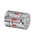
28 Servo-Insert Couplings Basics Backlash-free Servo-Insert Couplings Backlash-free Servo Insert Couplings are used in mechanical engineering, where shock absorption is requested and pluggable coupling solutions are applied. Special Features Backlash-free Plug-in type Vibration damping Torques from lb-in Compensation of radial, axial and angular misalignment Electrically isolating Common Applications: Encoder Precision drives Feed drives Grinding and milling spindles Machine tools Packing machines Robotics Transfer lines Multi-spindle heads Wood processing equipment Textile machinery Conveying equipment Linear motion Measuring equipment and control technology Test rigs 28
29 Hoist
30 Automation


31 Overview Servo-Insert Couplings EK/GS DK/GS ADS Miniature Servo-Insert Coupling with set-screw style hubs Page 32 Servo-Insert Coupling with clamping style hubs and single slit Page 34 Servo-Insert Coupling with clamping style hubs and dual slits Page 36 ADS/R ASS/A Servo-Insert Coupling interchangeable with competitive brands Page 38 Servo-Insert Coupling with External Shrink Disc Page 40 31

32 Backlash-free Servo-Insert Couplings EK/GS øa = Outer diameter ød1 H7 = Bore diameter ød2 H7 = Bore diameter C = Guided length shaft bore E = Mounting dimension for elastomeric spider I = Clamp srew centerline L ± 0.08 = Total length G = Clamping screws C 1 = Bore tolerance for D 1 C 2 = Bore tolerance for D 2 Technical Data Size L Ø A E Ø D1 H7 C1 Ø D2 H7 C2 C I G T KN M A n max J Weight 10-6 lbin ±0.079 Inch lb-in rpm 2 lbs xM xM xM xM xM xM Moment of inertia and weight (mass) are calculated with reference to the largest bore size. Example: EK/GS Size Ø D1 Ø D2 Further details* EK/GS XXXXX 32
33 L Technical Data O A O D1 H7 I O D2 H7 G (DIN 916) TKN = Nominal torque J = Moment of inertia MA = Tightening torque of screws m = Weight per hub nmax = Max. rotational speed 120 C E C keyway acc. DIN optionally Sectional view Torque values based on metric shaft diameters Size Ø 2 Ø 3 Ø 4 Ø 5 Ø 6 Ø 7 Ø 8 Ø 9 Ø 10 Ø 11 Ø 12 Ø 13 Ø 14 Ø 15 Ø 16 Ø 17 Ø 18 Ø 20 Ø 24 Ø Bore range D1/D2 and corresponding transmissible torque values (lb-ins) of the coupling Characteristics Compact design Economically priced Axial assembly Vibration damping Electrically isolating 33
34 Backlash-free Servo-Insert Couplings DK/GS øa = Outer diameter ød1 H7 = ød2 H7 = Bore diameter Bore diameter øh = Clearance diameter C = Guided length shaft bore E = Mounting dimension for elastomeric spider I = Radius to clamp screw K = Radius to clamp screw L ± 0.08 = Total length G = Clamping screw C 1 = Bore tolerance for D 1 C 2 = Bore tolerance for D 2 Technical Data Size L Ø A K Ø H E Ø D1 H7 C1 Ø D2 H7 C2 C I G T KN M A n max J Weight 10-6 lbin ±0.079 Inch mm lb-in lb-in rpm 2 lbs M M M Moment of inertia and weight (mass) are calculated with reference to the largest bore size. Example: DK/GS Size Ø D1 Ø D2 Further details* DK/GS XXXXX 34
35 I L G (DIN EN ISO 4762) K Technical Data T KN = Nominal torque J = Moment of inertia M A = Tightening torque of screws n max = Max. rotational speed Ø A Ø D1 H7 Ø D2 H7 Ø H C E C keyway acc. DIN optionally Sectional view Torque values based on metric shaft diameters Size Ø 2 Ø 3 Ø 4 Ø 5 Ø 6 Ø 7 Ø 8 Ø 9 Ø 10 Ø Bore range D1/D2 and corresponding transmissible torque values (lb-ins) of the coupling Characteristics Economical clamping hub Easy to install Electrically isolating Vibration damping Fail-safe design Plug-in type - axial installation 35
36 Backlash-free Servo-Insert Coupling ADS øa = Outer diameter ød1 H7 = Bore diameter ød2 H7 = Bore diameter øh = Clearance diameter C = Guided length shaft bore E = Mounting dimension for elastomeric spider I = Radius to clamp screw K = Radius to clamp screw L ± 0.08 = Total length G = Clamping screw C 1 = Bore tolerance for D 1 C 2 = Bore tolerance for D 2 Technical Data Size L Ø A K Ø H E Ø D1 H7 C1 Ø D2 H7 C2 C I G T KN M A n max J Weight 10-6 lbin ±0.079 Inch lb-ft rpm lbs M M M M M M M Moment of inertia and weight (mass) are calculated with reference to the largest bore size. Example: ADS Size Ø D1 Ø D2 Further details* ADS XX 36
 Sectional view Torque values based on metric shaft diameters Size Ø 10 Ø 11 Ø 13 Ø 14 Ø 16 Ø 18 Ø 19 Ø 20 Ø 24 Ø 25 Ø 28 Ø 30 Ø 32 Ø")
37 keyway acc. DIN optionally Technical Data I L K T KN = Nominal torque J = Moment of inertia M A = Tightening torque of screws n max = Max. rotational speed Ø A Ø D1 H7 Ø D2 H7 Ø H C E C G (DIN EN ISO 4762) Sectional view Torque values based on metric shaft diameters Size Ø 10 Ø 11 Ø 13 Ø 14 Ø 16 Ø 18 Ø 19 Ø 20 Ø 24 Ø 25 Ø 28 Ø 30 Ø 32 Ø 35 Ø 38 Ø 40 Ø 42 Ø 44 Ø 48 Ø 50 Ø Bore range D1/D2 and corresponding transmissible torque values (lb-ins) of the coupling Characteristics Clamping hub for higher torque Simple assembly Vibration damping Electrically isolating 37
38 Backlash-free Servo-Insert Coupling ADS/R øa = Outer diameter ød1 H7 = Bore diameter ød2 H7 = Bore diameter øh = Clearance diameter C = Guided length shaft bore E = Mounting dimension for elastomeric spider I = Radius to clamp screw K = Radius to clamp screw L ± 0.08 = Total length G = Clamping screw C 1 = Bore tolerance for D 1 C 2 = Bore tolerance for D 2 Technical Data Size L B K Ø A Ø H E Ø D1 H7 C1 Ø D2 H7 C2 C I G T KN M A n max J Weight 10-6 ±0.079 Inch lb-in lb-in rpm lb-in 2 lbs M M M M M M M Moment of inertia and weight (mass) are calculated with reference to the largest bore size. Hub design; up to size 19 single slit, from size 24 with dual slit. Example: ADS/R Size Ø D1 Ø D2 Further details* ADS/R XX 38
39 L K I G (DIN EN ISO 4762) Technical Data T KN = Nominal torque J = Moment of inertia M A = Tightening torque of screws n max = Max. rotational speed Ø A Ø D1 H7 Ø D2 H7 Ø H C E C keyway acc. DIN optionally Sectional view Torque values based on metric shaft diameters Size Ø 11 Ø 14 Ø 16 Ø 18 Ø 19 Ø 20 Ø 24 Ø 25 Ø 28 Ø 30 Ø 32 Ø 35 Ø 38 Ø 40 Ø 42 Ø 45 Ø 48 Ø 50 Ø Range of applications Bore range D1/D2 and corresponding transmissible torque values (lb-ins) of the coupling Characteristics Dimensionally equivalent to competitive versions 39
40 Backlash-free Servo-Insert Coupling ASS/A øa = Outer diameter ød1 H7 = Bore diameter ød2 H7 = Bore diameter C = Guided length shaft bore E = Mounting dimension for elastomeric spider G = Screw L ± 0.08 = Total length M = Clamp collar width - relaxed condition C 1 = Bore tolerance for D 1 C 2 = Bore tolerance for D 2 Technical Data Size L M Ø A E Ø D1 H7 C1 Ø D2 H7 C2 C G T KN M A n max J Weight ±0.079 Inch mm lb-in rpm lb-in 2 lbs M M M M M M M Moment of inertia and weight (mass) are calculated with reference to the largest bore size. Example: ASS/A Size Ø D1 Ø D2 Further details* ASS/A XX 40
41 L Technical Data T KN = Nominal torque J = Moment of inertia M A = Tightening torque of screws n max = Max. rotational speed Ø A Ø D1 H7 Ø D2 H7 G (DIN EN ISO 4762) M C E C M G (DIN EN ISO 4762) Sectional view Torque values based on metric shaft diameters Size Ø 6 Ø 10 Ø 11 Ø 13 Ø 14 Ø 15 Ø 17 Ø 19 Ø 20 Ø 24 Ø 25 Ø 27 Ø 30 Ø 32 Ø 36 Ø 38 Ø 41 Ø 42 Ø 44 Ø 48 Ø 50 Ø Bore range D1/D2 and corresponding transmissible torque values (lb-ins) of the coupling Characteristics High torque transmission Optimal concentricity Vibration damping Easy to install Electrically isolating 41
42 Technical Information Servo-Insert-Couplings Backlash-free Servo-insert Coupling Technical Description The couplings can be fine-tuned to the specific application requirements in terms of torsional stiffness and vibration behavior by selecting from various color coded elastomeric spiders having different grades of shore hardness. Technical terms for the coupling design Pre-Compression: The elastic pre-compression varies depending on the shore hardness of spiders, the size of the coupling and the machining tolerances. From this the axial insertion force results : From light (as a push fit with torsionally soft spider) to heavy (with high pre-compression with torsionally stiff spider) T kn Nominal Torque of coupling (lb-in): Continuous torque which can be transmitted throughout the entire speed range, taking into consideration operational factors such as ambient temperatures and torsional stiffness. T kmax Maximum Torque of coupling (lb-in): Torque to be transmitted 1 x 10 5 times as a peak load or 5 x 10 4 times as an alternating load during the entire life of the coupling taking into consideration factors such as temperatures, torsional stiffness and shock loading. Spider durometer (shore hardness) color Material Allowable temperarure range F continous max. temp. temperature short term Available for Size Typical applications 80 SH A blue polyurethane -58 to to Drives in electronic measuring systems; backlash free when pre compressed 92 SH A yellow polyurethane -40 to to Main spindle drives, backlash free when pre-compressed 98 SH A red polyurethane -22 to to Positioning drives, backlash free when pre-compressed 64 SH D-H green hytrel 64 SH D green polyurethane -58 to to to to Machine tool spindles, control drives, lead units, planetary gearboxes, heavy loads, torsionally stiff, high ambient temperature, water proof 42
43 Technical Information Servo-Insert-Couplings Technical Information - Spiders Size Spider Shore Max. speed (rpm) for Type torque lb-in Scale DK/GS; ADS; ADS/R static torsional stiffness dynamic torsional stiffness radial stiffness EK/GS ASS/A TkN Tkmax lb-in/rad lb-in/rad lb-in/inch 80 A A A A A A H A A A H A A A H A A A H A A D A A H A A H A A D A A D


44 Preview Backlash free compensating coupling ICL Backlash free compensating coupling SMC Customer: Field of application: Linear units manufacturer Direct drive of mounted hollow shafts Task: The usual use of metal bellows couplings as a connection device required extensive use of additional components, making the overall system quite cumbersome. By eliminating any misalignment compensating devices and substituting only rigid connection methods (i.e. Locking Assemblies) the axial loads due to thermal expansion and radial misalignments led to increased bearing loads and, therefore, premature bearing wear. The GERWAH solution: The combination of a locking assembly connection with a shaft coupling allows the space saving assembly of the drive directly at the hollow shaft. A metal bellows balances radial and axial misalignments and reduces the bearing load. Numerous components and their related misalignment sources can be eliminated due to the direct connection of the drive shaft and the supported hollow shaft. The installation of the coupling is possible with a minimal expenditure of time as it is mounted pre-assembled. Optimizing the initial load position relieves the loading on the ball bearings. Further fields of application: Automation industry Customer: Field of application: Machine tool manufacturer Main spindle drive with high rotational speeds, machines for drilling and milling Difficulty: Customary plug-in type couplings feature a limited torsional stiffness. When using a PU-spider often wear problems occur due to the loads during operation. The result is a premature wear. Our solution: Utilization of an all metal coupling with single side or double adaptor flange. The all metal coupling system was developed to be a highly dynamic, torsionally rigid coupling, allowing for high rotational speeds with minimum unbalance and runout. The application: The developed coupling is used in the main spindle drive of a machining center with a speed range of rpm. Due to the special construction, highest rotational speeds can be transmitted without vibration. The failure rate and maintenance intervals can be dramatically reduced. Linear units Attachment drives Materials handling technology Robotics 44
45 Line Shafts Basics Backlash-free Line Shafts Torsionally stiff and flexible line shafts are used in applications where torque and rotational motion combined with the highest possible angular precision should be transmitted or considerable distances between shafts need to be bridged. The application range of line shafts covers almost all technical areas, where mechanical power transmission and stiffness are important: Torsionally flexible line shafts with elastomeric spider Absolutely backlash-free Installation length up to 20 feet possible Compensation of axial, radial and angular misalignment Cost-effective, simple assembly Maintenance free Variable length of the intermediate (or line) steel or aluminum tube Torsionally stiff line shafts with metal bellows Absolutely backlash-free Installation length up to 20 feet possible Compensation of axial, radial and angular misalignment Aluminium lightweight construction up to size 200 Optional with CFK-tube Maintenance free, no wear Universal joint tube version available Special stainless steel bellows Excellent power transmission High torsional stiffness and misalignment compensation Optimal moment of inertia Additional balancing holes for better concentricity Temperature range -22 F to 212 F. Excellent torsional rigidity Backlash free elastomeric spider Excellent transmission of torque and compensation of misalignment High transmission accuracy Temperature range -22 F to F 45

46 Packaging Machine


47 Overview Line Shafts ADS-ZW ADS/B-ZW ASS/A-ZW Servo-Insert Coupling with clamping style hubs Page 48 Servo-Insert Coupling with clamping style hubs and Shrink Disc Page 50 Servo-Insert Coupling with clamping Shrink Disc Page 52 ASS/B-ZW ADS/H-ZW AKN-ZW Servo-Insert Coupling with Shrink Disc, outside mounting Page 54 Servo-Insert Coupling with clamping style hubs in half shell construction Page 56 Metal Bellows Coupling with clamping style hubs in flange construction Page 58 47
48 Backlash-free Line shafts ADS-ZW øa = Outer diameter ød1 H7/øD2 H7 = Bore diameter øh = Clearance diameter ør = Tube diameter C = Guided length shaft bore E = Mounting dimension for elastomeric spider I/K = Radius to clamp screw L ± 0.08 = Total length L1 = Coupling length G/G1 = Clamping screw X = Distance between shaft ends C 1 = Bore tolerance for D 1 C 2 = Bore tolerance for D 2 Size L L 1 K Ø A Ø H E Ø R Ø D1 H7 C1 Ø D2 H7 C2 C I G G 1 ±0.079 Inch mm M4 M M5 M M6 M M8 M M10 M M10 M M12 M12 Characteristics Cost-efficient design Easy to install Electrically isolating, damping Backlash-free Fail-safe design Example: ADS-ZW Size Length Ø D1 Ø D2 Further details* ADS-ZW 14/ XX 48
49 Technical Data I L1 L G1 keyway acc. DIN optionally K T KN = Nominal torque M A = Tightening torque of screws Ct = Torsional stiffness per meter n max = Max. rotational speed Ø A Ø D1 H7 Ø D2 H7 Ø H C E C X = L -2 x C Ø R G (DIN EN ISO 4762) Sectional view Technical Data Size C t T KN M A Hubs lb-in/rad lb-in lb-in Material Al AI AI AI AI St St Torque values based on metric shaft diameters Size Ø 10 Ø 11 Ø 13 Ø 14 Ø 16 Ø 18 Ø 19 Ø 20 Ø 24 Ø 25 Ø 28 Ø 30 Ø 32 Ø 35 Ø 38 Ø 40 Ø 42 Ø 44 Ø 48 Ø 50 Ø Bore range D1/D2 and corresponding transmissible torque values (lb-ins) of the coupling 49

50 Backlash-free Line shafts ADS/B-ZW øa = Outer diameter ød1 H7/øD2 H7 = Bore diameter øh = Clearance diameter ør = Tube diameter C = Guided length shaft bore E = Mounting dimension for elastomeric spider I/K = Radius to clamp screw L ± 0.08 = Total length L1 = Coupling length G/G1 = Clamping screw X = Distance between shaft ends C 1 = Bore tolerance for D 1 C 2 = Bore tolerance for D 2 Size L L 1 K Ø A Ø H E Ø R Ø D1 H7 C1 Ø D2 H7 C2 C I G G 1 ±0.079 Inch mm M4 M M5 M M6 M M8 M M10 M M10 M M12 M10 Characteristics Cost-efficient design Easy to install Electrically isolating, damping Backlash-free, fail-safe design For higher torques Example: ADS/B-ZW Size Length ADS/B-ZW 14/3.125 Ø D1 Ø D2 Further details* XX 50
51 Technical Data I L1 L G1 keyway acc. DIN optionally K T KN = Nominal torque M A = Tightening torque of screws C t = Torsional stiffness per meter n max = Max. rotational speed Ø A Ø D1 H7 Ø D2 H7 Ø H C E C Ø R X = L - 2 x C G (DIN EN ISO 4762) Sectional view Technical Data Size C t T KN M A (G) M A (G1) n max Hub/circlip lb-in/rad lb-in lb-in lb-in rpm Material Al/St Al/St Al/St Al/St Al/St St/St St/sSt Torque values based on metric shaft diameters Size Ø 10 Ø 11 Ø 13 Ø 14 Ø 16 Ø 18 Ø 19 Ø 20 Ø 24 Ø 25 Ø 28 Ø 30 Ø 32 Ø 35 Ø 38 Ø 40 Ø 42 Ø 44 Ø 48 Ø 50 Ø Bore range D1/D2 and corresponding transmissible torque values (lb-ins) of the coupling 51
52 Backlash-free Line shafts ASS/A-ZW øa = Outer diameter ød1 H7/øD2 H7 = Bore diameter ør = Tube diameter C = Guided length shaft bore E = Mounting dimension for elastomeric spider L ± 0.08 = Total length L1 = Coupling length G = Clamping screws G1 = Clamping screws X = Distance between shaft ends C 1 = Bore tolerance for D 1 C 2 = Bore tolerance for D 2 Size L L 1 Ø A E Ø R Ø D1 H7 C1 Ø D2 H7 C2 C G G 1 ±0.079 Inch mm M3 M M4 M M5 M M5 M M6 M M8 M M10 M10 Characteristics For higher torques Optimal concentricity Electrically isolating, damping Backlash-free Fail-safe design Example: ASS/A-ZW Size Length ASS/A-ZW 14/3.125 Ø D1 Ø D2 Further details* XX 52
53 L1 L G1 Technical Data T KN = Nominal torque M A = Tightening torque of screws C t = Torsional stiffness (tube) n max = Max. rotational speed Ø A Ø D1 H7 Ø D2 H7 G C E C Ø R X = L - 2 x C Sectional view Technical Data Size C t T KN M A (G) M A (G1) n max Hubs lb-in / rad lb-in lb-in lb-in rpm Material Al AI AI AI AI St St Torque values based on metric shaft diameters Size Ø 6 Ø 10 Ø 11 Ø 13 Ø 14 Ø 15 Ø 17 Ø 19 Ø 20 Ø 24 Ø 25 Ø 27 Ø 30 Ø 32 Ø 36 Ø 38 Ø 41 Ø 42 Ø 44 Ø 48 Ø 50 Ø Bore range D1/D2 and corresponding transmissible torque values (lb-ins) of the coupling 53

54 Backlash-free Line shafts ASS/B-ZW øa = Outer diameter ød1 H7/øD2 H7 = Bore diameter ør = Tube diameter C = Guided length shaft bore E = Mounting dimension for elastomeric spider L ± 0.08 = Total length L1 = Coupling length G = Clamping screws G1 = Clamping screws X = Distance between shaft ends C 1 = Bore tolerance for D 1 C 2 = Bore tolerance for D 2 Size L L 1 Ø A E Ø R Ø D1 H7 C1 Ø D2 H7 C2 C G G 1 ±0.079 Inch mm ,73 M3 M ,98 M4 M ,18 M5 M ,38 M5 M ,77 M6 M ,97 M8 M ,20 M10 M10 Characteristics For higher torques Optimal concentricity Electrically isolating, damping Backlash-free Fail-safe design Example: ASS/B-ZW Size Length ASS/B-ZW 14/3.125 Ø D1 Ø D2 Further details* XX 54
55 L1 L G1 Technical Data T KN = Nominal torque M A = Tightening torque of screws C t = Torsional stiffness (tube) n max = Max. rotational speed Ø R Ø A Ø D1 H7 Ø D2 H7 G C E C X = L - 2 x C Sectional view Technical Data Size C t T KN M A (G) M A (G1) n max Hubs lb-in/rad lb-in lb-in lb-in rpm Material Al AI AI AI AI St St Torque values based on metric shaft diameters Size Ø 6 Ø 10 Ø 11 Ø 13 Ø 14 Ø 15 Ø 17 Ø 19 Ø 20 Ø 24 Ø 25 Ø 27 Ø 30 Ø 32 Ø 36 Ø 38 Ø 41 Ø 42 Ø 44 Ø 48 Ø 50 Ø Bore range D1/D2 and corresponding transmissible torque values (lb-ins) of the coupling 55
56 Backlash-free Line shafts ADS/H-ZW øa = Outer diameter ød1 H7/øD2 H7 = Bore diameter øh = Clearance diameter ør = Tube diameter C = Guided length shaft bore E = Mounting dimension for elastomeric spider I/K = Basic dimension L ± 0.08 = Total length G = Clamping screws X = Distance shafts C1 = Clamp collar width C2 = Bore tolerance for D1 C3 = Bore tolerance for D2 Size L K Ø A Ø H E Ø R Ø D1 H7 C2 Ø D2 H7 C3 C C 1 I G ±0.079 Inch mm M M M M M M M12 Characteristics For higher torques Optimal concentricity Electrically isolating, damping Backlash-free Fail-safe design Example: ADS/H-ZW Size Length ADS/H-ZW 14/3.125 Ø D1 Ø D2 Further details* XX 56
57 Technical Data T KN = Nominal torque I C E L keyway acc. DIN optionally K K M A = Tightening torque of screws C t = Torsional stiffness (tube) n max = Max. rotational speed Ø A Ø D1 H7 Ø R Ø D2 H7 Ø H C1 X = L - ( 2 x C1 ) G (DIN EN ISO 4762) Sectional view Technical Data Size M A C t T KN n max Hubs lb-in lb-in/rad lb-in rpm Material Al AI AI AI AI St St Torque values based on metric shaft diameters Size Ø 10 Ø 11 Ø 13 Ø 14 Ø 16 Ø 18 Ø 19 Ø 20 Ø 24 Ø 25 Ø 28 Ø 30 Ø 32 Ø 35 Ø 38 Ø 40 Ø 42 Ø 44 Ø 48 Ø 50 Ø Bore range D1/D2 and corresponding transmissible torque values (lb-ins) of the coupling 57
58 Backlash-free Line shafts AKN-ZW øa = outer diameter øb = basic dimension ød1 H7/øD2 H7 = Bore diameter øe = pitch circle diameter ør = tube diameter C = max. shaft rack length I = Radius to clamp screw K = Radius to clamp screw L ± 0.08 = total length L1 = Coupling length L2 = Basic dimension G = Screw G1 = Screws X = distance shafts C 1 = Bore tolerance for D 1 C 2 = Bore tolerance for D 2 Size L Ø B Ø E Ø A L2 K Ø R Ø D1 H7 C1 Ø D2 H7 C2 C I L1 G G 1 ±0.079 Inch mm M5 4xM M6 6xM M8 6xM M10 8xM M12 8xM M12 8xM M12 8xM8 Characteristics Absolutely backlash-free and torsional stiff Installation lengths up to 20 feet Simplest assembly Drive shaft tube CFK (optional) Example: AKN-ZW Size Length AKN-ZW 18/20.0 Ø D1 Ø D2 Further details* XX 58
59 Technical Data I L2 L1 L X = L - ( 2 x L2 ) Ø A Ø E K T KN = nominal torque M A = tightening torque of screws C t = torsional stiffness (tube) n max = max. rotational speed Kr = radial max. approved Ø B Ø D1 H7 Ø R Ø D2 H7 misalignment radial Ka = max. approved misalignment axial Kw = max. approved misalignment angular C G1 (DIN 931) keyway acc. DIN optionally G (DIN 912) Sectional view Technical Data Size M A (G) M A (G1) C t T KN n max Tube/Hub lb-in lb-in 10 3 lb-in/rad lb-in rpm Material Al/ Al Al/ Al Al/ Al Al/ St Al/ St St/ St St/ St Size Misalignments Inch radial Inch axial Degree angular Kr Ka Kw Inch 0.04 Inch Inch 0.03 Inch Inch 0.03 Inch Inch 0.03 Inch Inch 0.03 Inch Inch 0.03 Inch Inch 0.04 Inch 2 Kr* Misalignment values refer radial per mtr./tube. Kw* Angular misalignment values refer to the total angular misalignment between the shafts to connect. 59
60 Backlash-free Metal Bellows Couplings Assembly Instructions Assembly Clean and degrease shaft ends and bores in hubs and check the tolerances. Insert both shaft ends into the hubs of the Metal Bellows Coupling. Firmly tighten the screws after examining the axial installation dimensions. The tightening torque of the screws and the maximum approved misalignment should not be exceeded (refer to the appropriate technical data table). Disassembly After loosening the backlash-free shaft hub connections, the drive can be pulled apart and the metal bellows coupling can be removed. Keyless bushings of series AK are forced off with a socket head cap screw. Alignment If several types of misalignment occur simultaneously, none of them must reach the maximal value but must be adjusted. The sum of all actual misalignments must not exceed 100 % (percentage of the maximum value). The diagram below shows how to adjust. The more precise the alignment, the more reserves are available to handle additional misalignments during the operation. This will have an advantageous effect on the durability, quietness and the accuracy of transmission. Please ask for our detailed assembly instructions. Ka axial radial Kr axial angular Kw 60
61 Backlash-free Metal Bellows Couplings Assembly Instructions Application: A bellows coupling CKN 80/61 has to be installed. The following misalignment values result from the installation situation: Kr = in. Ka = in. Kw = 0.2 Are the misalignment values for the CKN 80/61 acceptable? Selection: The tolerable misalignment values are: (cp. data sheet CKN): Krn = in. Kan = in. Kwn = 1.5 The allowable radial misalignment Kr = in. corresponds to 50% of the max. allowable value. The value Ka = in. corresponds to 20% of the max. allowable axial misalignment. The angular misalignment with Kw = 0.2 corresponds to 13% of the overall view. ΔKa radial misalignment (%) ΔKw angular misalignment (%) 0% 25% 50% 75% Diagram ΔKa axial misalignment (%) Interpretation by means of the diagram: Enter the calculated values in the diagram on the right side (dashed line). The combination of the different misalignment values is within the tolerable area. Interpretation by means of the empirical formula: 50% + 20% + 13% < 100%. The coupling can be installed. Empirical formula: DK r DK rm x 100 % + DK a DK an x 100 % + DK w DK wn x 100 % < 100 % 61
62 Backlash-free Servo-insert Coupling Assembly Instructions Assembly Hub Clean and degrease both shaft surface and hub bores and check the tolerances. As a standard, the bores are equipped with a fit ISO-H7. For the shafts, we recommend a transition fit, e.g. H7/g6 (see table below). When selecting other shaft fittings, the backlash should not exceed a maximum of Inch. Spider Slide a coupling hub onto each shaft end and tighten the screws after checking the axial dimensions. Refer to the appropriate technical table for the correct screw tightening torque. Hub Bump Tolerance (Inch) D1 & D2 (Inch) Bore Shaft above up to H6 g / / / / / / / / / / / / / / Coupling hub Spider 62
63 Firmly press the elastomer spider into one of the two hubs. A PU compatible grease such as Vaseline may be applied to ease assembly. The edges of the spider and the jaws of the coupling hubs are both chamfered for an easier or if applicable - blind assembly. The burls, located alternately on the teeth, ease the assembly and prevent the installation from being too tight. Now push in the second hub. Always keep within the clearance, so that the elastomer spider will not be preloaded, thereby insuring longer durability and electrical isolation. Hub Spider IMPORTANT: For application with high dynamic loading For application with high dynamic loading (frequent acceleration and reverse rotation) or high impact load (applications like presses and shredder) we recommend to use the support of the GERWAH team in doing the dimensioning and choosing the appropriate coupling. Hub elastic deformation Hub Spider Hub E 63
64 Backlash-free Servo-insert Coupling Assembly Instructions Alignment The picture below shows the three types of misalignments. The mounted coupling needs to be aligned. The more accurate the initial alignment, the better the coupling can absorb additional misalignments during operation. Durability and quietness are favorably influenced. If all three types of misalignment occur simultaneously, each type must not reach the maximum allowable value, but must be adjusted. The total amount of the actual misalignment types, expressed as a percentage of the maximum allowable value, must not exceed 100%. The diagram on the right side shows such an adjustment. radial misalignment Δ % 50 % 25 % 0 % Δ Ka angular missalignment (%) Δ axial misalignment Ka axial radial Kr angular Kw 64
65 Removal Remove the fastening screws, e.g. on the motor. Pull the drive unit, including the Servo Insert Coupling apart. A new spider or a spider with a different shore hardness can now be installed. After loosening the backlash-free shaft-hub-connection the hubs can be disassembled. Please ask for a detailed instruction sheet. Technical Information Spiders Misalignments Size Spider Shore scale axial Ka 1) radial Kr angular Kw Inch Inch Degree A A to A A A to A D A A to A D A A to A D A A to A D A A to D A A to D A A to D A A to D A A to D ) The Ka-values have to be added to the length of the size 65
66 GERWAH Line Shafts Assembly Instructions Alignment of the shafts: The picture shows the several types of misalignment. It is necessary to adjust the shafts before assembly. The more accurate the initial alignment, the better the shaft can absorb additional misalignments during operation. Durability of the line shafts and quietness of the drive are favourably influenced. In case all three types of misalignment occur simultaneously, each type must not reach the maximum allowable value, but have to be aligned. GERWAH can assist you with the correct adjustment of the combined misalignment. Installation: Clean and degrease the hubs of the line shafts and check the tolerances according to the respective design. The maximal diametrical clearance between hub and shaft must not exceed 0.03 mm or in. (not valid for sliding fits). According to the principle of construction, slide a coupling hub onto each shaft end and tighten the screws of the shaft-hubconnection after checking axial dimensions. Refer to the technical data to assure the correct wrench torque for the screws. The dimension of the shaft distance X should be maintained. Ka axial radial Kr angular Kw 66


67 Removal: Remove the locking screws of the hubs. If necessary, the push-off threads can be used to remove the backlash-free line shaft connections. In case the hub connection doesn t come off automatically, the connection can be removed by lightly applying a rubber hammer. Please ask for detailed assembly instructions or find information on Misalignments Servo Insert Line Shafts Size shafting Inch radial Inch axial Degree angular Kr Ka Kw Inches per ft ± Inch Inches per ft ± Inch Inches per ft ± Inch Inches per ft ± Inch Inches per ft ± Inch Inches per ft ± Inch Inches per ft ± Inch 1.5 Radial/parallel misalignment depends on the length of the tube. 67
68 Fax Inquiry Couplings On this page please explain the planned application of a coupling and we will propose our solution. Please send this page to: RINGFEDER POWER TRANSMISSION CORPORATION, USA Fax Application Planned use of the coupling (machine, machine group or plant): 2. Type of attachment (please tick/check) Clamping hub Internal keyless device Expanding hub Hub with set screw Flange mount 3. Shrink Disc Fanuc Acc. customer request Length (Inches) Bore D 1 (Inches) Keyway Outer diameter (Inches) Bore D 2 (Inches) Keyway 4. Shaft Misalignment Axial (Inches) Radial (Inches) Angular (Degree) 5. Drive Drive power P = HP Nominal torque of the drive Mt nom = lb-in Input speed n = rpm Peak torque of the drive Mt maxx = lb-in 6. Mass moment of inertia On the drive side 7. Environmental influences J A = lb-in 2 On the driven side J L = lb-in 2 Temperature in the area of the coupling Temp = F Special materials (e.g. stainless steel) Are there any impacts on the load side? No Slight Medium Heavy sonstige, besondere Einflüsse / other, special influences 8. Estimated demand 9. Target Price Production quantity Project Repair Number of items/p.a. $/Each Please send your offer to: Company Attention Address Phone Fax 68
69 Fax Inquiry Line-Shafts On this page please explain the planned application of a coupling and we will propose our solution. Please send this page to: RINGFEDER POWER TRANSMISSION CORPORATION, USA Fax Application Planned use of the coupling (machine, machine group or plant): 2. Type of attachment (please tick/check) Clamping hub Cone hub Expanding hub Hub with set screw Flange mount Acc. customer request 3. Length (Inches) Bore D 1 (Inches) Keyway Outer diameter (Inches) Bore D 2 (Inches) Keyway 4. Shaft Displacement Axial (Inches) Radial (Inches) Angular (Degree) 5. Drive Drive power P = HP Nominal torque of the drive Mt nom = lb-in Input speed n = rpm Peak torque of the drive Mt maxx = lb-in 6. Mass moment of inertia On the drive side J A = lb-in 2 On the driven side J L = lb-in 2 7. Environmental influences Temperature in the area of the coupling Temp = F Special materials (e.g. stainless steel) Are there any impacts on the load side? No Slight Medium Heavy Other, special influences 8. Estimated demand 9. Target Price Production quantity Project Repair Number of items/p.a. $/Each Please send your offer to: Company Attention Address Phone Fax 69
70 Notes 70


71 Delivery Program Locking Devices Locking Assemblies Locking Elements Shrink Discs Smart-Lock Damping Technology Friction Springs DEFORM plus DEFORM plus R Fluid Elastomeric Damper Special Solutions Shaft Couplings Locking Assemblies Flange Couplings Couplings Magnetic Couplings Metal Bellows Couplings Servo-Insert Couplings RING-flex torsionally rigid Disc Couplings Safety Couplings Line Shafts 71

72 RINGFEDER POWER TRANSMISSION CORPORATION 165 Carver Avenue, P.O. Box 691 Westwood, NJ 07675, USA Toll Free: Phone: Fax: RINGFEDER POWER TRANSMISSION
DIST. AUTORIZADO MEX (55) QRO (442) MTY (81) Edition 10/2005
 QRO (442) MTY (81) Edition 10/2005") dition /0 IST. UTORIZO X () 1 QRO (4) 1 9 0 TY (81) 8 4 G R W H T h e o m p a n y GRWH GmbH was founded in 10. The idea of new, innovative products has made GRWH a recognized partner in the machine tool
dition /0 IST. UTORIZO X () 1 QRO (4) 1 9 0 TY (81) 8 4 G R W H T h e o m p a n y GRWH GmbH was founded in 10. The idea of new, innovative products has made GRWH a recognized partner in the machine tool
PPG Series High Precision Gearbox. Datasheet
 PPG Series High Precision Gearbox Datasheet Version PPG-2014-01 http://www.primopal.com Description PrimoPal s PPG series High Precision Planetary Gearboxes are mainly used with kinds of servo motors and
MAAG TM PPU gear unit for roller presses, horizontal mills and kilns
 MAAG TM PPU gear unit for roller presses, horizontal mills and kilns 2 Our quality policy FLSmidth MAAG Gear is committed to creating long lasting relationships that establish us as a trustworthy, reliable
TT SERIES OD ORBITAL CUTTING & BEVELING MACHINES 1/8 TO 168 OD 1/9
 TT SERIES OD ORBITAL CUTTING & BEVELING MACHINES 1/8 TO 168 OD PRACTICAL TOOLS INC. P.O. Box 233 Aurora, ON L4G 3H3, Canada Phone: 905-727-0014 / 888-847-8880 Fax: 905-727-8483 info@practicaltoolsinc.com
B-Series Section Overview. Ball Screw Cutaway. UNI-LIFT Ball Screw Actuators provide high. 34
 B- Section Overview UNI-LIFT Actuators provide high efficiency and high speed in a linear positioning package up to 100 tons. The low friction ball screw and nut design provides longer life at load and
M-Series, Actuator Overview. Machine Screw Cutaway. UNI-LIFT Machine Screw Actuators offer precise. 12
 M-, Actuator Overview UNI-LIFT Machine Screw Actuators offer precise positioning, uniform lifting speeds and capacity up to 250 tons. Standard model configurations include upright or inverted units with
M40 Size 1.5/Size 1.5i Power Connectors
 M40 Size 1.5/Size 1.5i Power Connectors Approvals Tested acc. to DIN EN 61984 UL/CSA metallic connectors Number of ways: Contact diameter: Nominal current (VDE) / 20 C: Nominal current (UL): Nominal current
ALUMINIUM ROLLERS MADE IN ITALY
 ALUMINIUM ROLLERS MADE IN ITALY Alveolar aluminium rollers, diameter 60mm to 250mm (natural or anodized). Roller manufacturing will be completely based on customer's drawings. The rollers can be supplied
DÖRRIES SCHARMANN ECOSPEED HSK-A63/80 STARRAG WERKZEUGAUFNAHMEN TOOL HOLDERS HSK A63/80.
 DÖRRIES SCHRMNN ECOSPEED HSK-63/80 STRRG STC TOO 800X HODERS WERKZEUGUFNHMEN TOO HODERS HSK 63/80 www.haimer.com POWER SHRINK CHUCK HSK 63/80 (TPER 63 mm/fnge 80 mm) 10 4.5 D3 CERTIFICTE OF QUITY ll functional
NM, NMS. Close Coupled Centrifugal Pumps with flanged connections. Construction. Applications. Operating conditions. Motor
 lose oupled entrifugal Pumps The electropumps,, S, S series comply with the Regulation no. 7/ in force starting from.. European Materials omponents, S, S Pump casing ast iron ronze Lantern bracket asing
BORING KITS from Ø 6 mm up to 210 mm
 Bohrstar BORING KITS from Ø mm up to 0 mm Coupling system COUPING SCREW ARBOR BORING HEAD COUPING SCREW HIGH RIGIDITY By tightening the two cone shaped coupling screws, high axial forces are developed
Novax. Axial flow fans Standard and hot smoke
 Novax Axial flow fans Standard and hot smoke Product facts Product Axial flow fans with adjustable blades. ACN for duct installation ACW for heavy duty ACG free intake with connection to duct ACP free
E Series Back Pull Out End Scution. Centrifugal Pump DIN 24255
 Back Pull Out End Scution Centrifugal Pump DIN 24255 MARKET SECTORS Buidling Services, RHVAC, Agriculture, Civil, Industries Back Pull Out End Suction Centrifugal Pump DIN 24255 MATERIAL OF CONSTRUCTION
Standard pumps. Dimensions, weights Wilo-CronoLine-IL
 Standard pumps Dimensions, weights Wilo-CronoLine-IL Standard pumps Dimensions, weights Wilo-CronoLine-IL Subject to change without prior notice /7 WILO AG / WILO AG Special features/product advantages
NESD / NESE. SINGLE-STAGE SELF-COOLED CENTRIFUGAL PUMPS TO STANDARD EN (NPE 44121) High-temperature water OPERATING LIMITS APPLICATIONS
 High-temperature water OPERATING LIMITS APPLICATIONS") OERATING LIMITS Flow up to: Head up to: 9 m CE Service pressure up to: up to bar* Temperature: min: C* / max: C* *: depending on model NESD / NESE SINGLE-STAGE SELF-COOLED CENTRIFUGAL UMS TO STANDARD EN
OERATING LIMITS Flow up to: Head up to: 9 m CE Service pressure up to: up to bar* Temperature: min: C* / max: C* *: depending on model NESD / NESE SINGLE-STAGE SELF-COOLED CENTRIFUGAL UMS TO STANDARD EN
Trocar Systems. Complete and efficient. Trocar systems
 Trocar Systems Complete and efficient Trocar systems Quality workmanship: PAJUNK Trocar systems Requirements for a trocar system vary greatly. The type and length of the respective surgical procedure has
ROUNDO Section Bending Machines Type R-1 through R-21-S
 ROUNDO Section Bending Machines Type R-1 through R-21-S Friläggas 1 Roundo Section Bending Machines - Largest selection on the market ROUNDO is the worlds leading manufacturer of plate and section bending
SLANT BED CNC TURNING CENTER
 1 SLANT BED CNC TURNING CENTER DESCRIPTION FTC-300 FTC-350 FTC-350L FTC-350XL FTC-350LY Swing Over Bed mm Ø 550 Ø 600 Ø 600 Ø 600 Ø 600 Max. Turning Diameter mm Ø 300 Ø 350 Ø 350 Ø 350 Ø 350 Max. Turning
PUMP. Type EVM APPLICATIONS MATERIALS TECHNICAL DATA. Washing system Water treatment plants Reverse Osmosis system Some chemical applications
 PUMP Type APPLICATIONS Washing system Water treatment plants Reverse Osmosis system Some chemical applications Conditioning systems Heating systems Industrial boilers Pressure boosting for industrial systems
Conduit Entry System. At a Glance. FWS Assembly. 1. Fast and Easy Assembly. 2. Easy to Maintain. 3. Flexible
 Conduit Entry System At a Glance CONFIX FWS The 90 angled conduit fitting CONFIX FWS is perfect for installation of parallel corrugated cable protection conduits, e.g. in machines, control panels or other
SMART MOTION C A T A L O G 2009:1
 SMART MOTION C A T A L O G 2009:1 Which arm do you need? To ensure that the balancing arm you order meets your expectations it is important to consider the following aspects. 1. Which type? PARALLEL ARM
fiber optic through-beam and dif. reflection sensors
 ipf electronic gmbh Kalver Straße 25 27 through-beam sensors diffuse reflection sensors accessories fiber optic through-beam and dif. reflection sensors plastic optic fibers 1800 1 2 1800 plastic fiber
Novenco Axial Flow Fans. Novax St andard and hot Smoke
 Novenco Axial Flow Fans Novax St andard and hot Smoke Product facts Product Axial flow fans with adjustable blades. ACN for duct installation ACG free intake with connection to duct ACP free suction and
Data sheet: Wilo-CronoNorm-NL 80/200-3/4
 Data sheet: Wilo-CronoNorm-NL /-3/ Pump curves H/m 1 1 1 1 NPSH/m,5, 1,5 1,,5 P /kw 5 3 1 3 5 55% % 5% 7% 7% 7,9% 1 5 15 5 3 35 3 5 1 3 5 7% 7,3% 7% 7% 77,9% 7,% 7,% Ø 17 Eff. 7,9% Ø 1 Ø 19 7% Ø 19 Ø 1
Sensyflow P. Thermal air-mass flowmeter for test rigs and quality assurance 10/ EN. Function and System Design
 Sensyflow P Thermal air-mass flowmeter for test rigs and quality assurance 10/1-6.8 EN Direct mass flow measurement Wide measuring range (1:0) High measuring accuracy measuring deviation < 1 % of measured
Max. flow absorbed (l/mn) Torque (N.m/bar) R
 Torque (N.m/bar) R") M series motors Characteristics of the m series motors Motor model Displacement (cc/rev) Continuous max. speed (1) (rpm) Intermittent max. speed (1) (rpm) Max. flow absorbed (l/mn) Torque (N.m/bar) Torque
M series motors Characteristics of the m series motors Motor model Displacement (cc/rev) Continuous max. speed (1) (rpm) Intermittent max. speed (1) (rpm) Max. flow absorbed (l/mn) Torque (N.m/bar) Torque
CAPILLARY DIAL THERMOMETERS TYPE TXC
 CAPILLARY DIAL THERMOMETERS TYPE TXC TYPE DRAWING DIMENSIONS mm A TXCxxxXA B 38 37 45 45 55 C 13 13 13 13 13 B B 41 40 51 51 57 C 13 13 13 13 13 TXCxxxXB D 86 110 132 196 285 D B 33 29 31 32 45 C 13 13
LEVELTEC ENGINEERING PTY LTD
 LEVELTEC ENGINEERING PTY LTD AUSTRALIAN DISTRIBUTOR FOR PC ELECTRIC PLUGS & SOCKETS PCE INDUSTRIAL PLUGS, SOCKETS AND CONNECTORS Industrial & Event CEE 16-125A 110-500v AC Switched Interlocked or Pilot
grinding wheels 322 z Cloth z With centre hole z Combi z Convolute z Unitized z Spindle mounted
 320 grinding wheels z With centre hole 322 z Cloth 322 z Tex 326 z CSD 329 z Combi 330 z Convolute 332 z Unitized 334 z Spindle mounted 338 z Cloth 338 z Tex 342 z Combi 345 z CSD 348 z Unitized 349 Cibo
Perfect sealing, a guarantee of economy
 RCS Compressed air Perfect sealing, a guarantee of economy 1 2 3 he problem 15 to 30% of compressed air is lost by leakage between the compressor and the tool. he calculation A 1mm hole in your circuit
teckentrup-sperrkant The Original
 teckentrup-sperrkant The Original New NSK detent-edged washer Innovative screw locking technology Reliable screw locking protects against loosening and unscrewing where high vibration is present Settling
MIG/MAG Welding Torch MB 401 D / MB 501 D. liquid-cooled. ABICOR BINZEL. The right welding torch for every job!
 MIG/MAG Welding Torch MB 401 D / MB 501 D liquid-cooled C E R DIN EN ISO 9001 Q M T - I F S I Y E T S D E M ABICOR BINZEL. The right welding torch for every job! BINZEL liquid cooled welding torches incorporate
teckentrup-sperrkant The Original
 teckentrup-sperrkant The Original www.teckentrup.de New Serrated Locking Washer NSK Innovative Screw and Bolt Locking Technology» Reliable bolt locking at low and high preload forces» Locking function
recool for lathes Fast and easy retrofitting to internal cooling with oil and emulsion
 recool for lathes Fast and easy retrofitting to internal cooling with oil and emulsion www.rego-fix.com External flood cooling Peripheral cooling Internal cooling The differences of wet and dry machining
UTS. UTS : Your first choice in waterproof connectors! Description. IP68/IP69K - Plastic connector
 Description IP68/IP69K - Plastic connector UTS series is a range of industrial plastic circular connectors offering IP68/IP69K water protection. 4 shell s - up to 32 contact positions - are available with
CEF POLYMERES. Spring. CEF POLYMERES sa.com DT.STRA.E l Fv F1 F. Strocke (S)
") Spring S Sv S 0 Sv Série 0R 5R R 6 R 700R CR 0 R 4 M M 167 M Strocke Max. 35% % % 25% % U90 % 9 UR % l S Creep value compression max 4 6% 3 5% 5 7% 7 9% 8 % 5 6% 6 8% l Fv F1 F Strocke (S) The value on
Spring S Sv S 0 Sv Série 0R 5R R 6 R 700R CR 0 R 4 M M 167 M Strocke Max. 35% % % 25% % U90 % 9 UR % l S Creep value compression max 4 6% 3 5% 5 7% 7 9% 8 % 5 6% 6 8% l Fv F1 F Strocke (S) The value on
Step drills And, with higher dimensional precision the drills will last considerably longer while maintaining the precise process tolerances.
 » STEP DRILLS Step drills The flutes of RUKO high performance step drills are CBN ground from the solid hardened form. Because CBN (cubical boron nitride) is a much harder abrasive than even silicium carbide
Other variations which are not mentioned in this document are on demand (if possible).
.") GENERAL INFORMATION This specification document is for gas-filled thermometers manufactured by: STIKO, Industrieweg 5, 9301 LM Roden, The Netherlands. STIKO is a manufacturer of mechanical instruments
GENERAL INFORMATION This specification document is for gas-filled thermometers manufactured by: STIKO, Industrieweg 5, 9301 LM Roden, The Netherlands. STIKO is a manufacturer of mechanical instruments
centrotex / captex / mandotex
 UK N-OV SYSTMS centrotex standard size M. Machine adapter with short taper / cylinder fit Short taper 2 V S V S J M J M Spindle nose U 2-6 2-8 P170 P220 Outer Ø 2 [mm] 73 g7 76 g7 85 g7 91 g7 101 g7 110
GEAR PUMPS. Displacement from 10 to 100 ccm Pressure up to 290 bar Speed from 350 to 3200 RPM
 Displacement from 10 to 100 ccm Pressure up to 290 bar Speed from 350 to 3200 PM GEA PUMPS Q2 Gear Pump Catalogue Q2 TABE OF CONTENTS DESCIPTION......................................................................................................................
COMPETENCE IN PRECISION AND QUALITY STEP DRILLS
 COMPETENCE IN PRECISION AND QUALITY STEP DRILLS Product information The flutes of new RUKO high performance step drills are CBN ground from the solid hardened form. Because CBN (cubical boron nitride)
Laparoscopic Reusable Trocars and Sleeves
 High quality trocars and sleeves are essential during multi-puncture, minimally invasive surgical procedures. Our wide range of reusable trocars and sleeves are more economically beneficial and technologically
Klinger Manometer Serie 200
 Klinger Manometer Serie 200 All stainless steel Bourdon tube pressure gauges watertight casing, dry or liquid filled execution; NS 63-100 150 200-250; Ranges included between -1 and 1.600 bar. The instruments
TECHNOLOGY FOR THE WELDER S WORLD. MIG/MAG CATALOG 4.1. MIG/MAG Welding Technology for all Metalworking Industries.
 TECHNOLOGY FOR THE WELDER S WORLD. MIG/MAG CATALOG 4.1 MIG/MAG Welding Technology for all Metalworking Industries. www.binzel-abicor.com Index MIG/MAG welding torches (wear parts system MB) MB EVO PRO
MIG/MAG Welding Torch MB 401 D / MB 501 D. liquid cooled. BINZEL. The right welding torch for every job! For welding and cutting come to the point.
 MIG/MAG Welding Torch MB 401 D / MB 501 D liquid cooled C E R DIN EN ISO 9001 Q M T - I F S I Y E T S D E M BINZEL. The right welding torch for every job! BINZEL liquid cooled welding torches incorporate
Medical technology Main catalog. Medicalline Medical industry connectors
 Medical technology Main catalog Medicalline Medical industry connectors STÄUBLI ELECTRICAL CONNECTORS Long-term solutions Expert connections Stäubli Electrical Connectors is a leading international manufacturer
Stainless Steel Gas Springs
 Stainless Steel Gas Springs Gas Springs in 4 (V2A) Stainless Steel As well as its very extensive range of standard adjustable force gas springs ACE can offer a wide range of stainless steel gas springs.
Case studies Vertical bearing GGG40 (GJS )
") Vertical bearing GGG40 (GJS-400-15) Machine: MC HSK63 Material: GGG 40 (EN-GJS-400-15) Parts/Year: ca. 100 000 Pre-machining: boring Coolant : Minimum quantity lubrication (MQL) Ø 33N5 x 142mm MQL CircoTec
Vertical bearing GGG40 (GJS-400-15) Machine: MC HSK63 Material: GGG 40 (EN-GJS-400-15) Parts/Year: ca. 100 000 Pre-machining: boring Coolant : Minimum quantity lubrication (MQL) Ø 33N5 x 142mm MQL CircoTec
An Urgent Bulletin from CSA Group
 An Urgent Bulletin from CSA Group Occupational Health & Safety Products No. 114 Effective Date: June 1, 2019 Date: May 24, 2018 Apply Before December 1, 2018 Announcing: Publication of ASTM F2413-17 Standard
Kit Potentiometer Rotational Analog Displacement Sensor
 Kit Potentiometer Rotational nalog Displacement Sensor FETURES Conductive plastic potentiometer technology, infinite resolution nalog or digital output Low height High flexibility of wires pplicable standards:
SOURIAU Extends its High Density Offer with Size #26 Contact Technology
 SOURIU xtends its Offer with Size #26 ontact Technology SOURIU brings to market a lightweight, robust and reliable 8ST High ensity solution from the smallest to the largest. reliable & robust solution
from 500 to 5000 RPM GEAR PUMPS P23
 Displacement Pressure Speed from 0,80 to 11,80 ccm up to 310 bar from 500 to 5000 PM GEA PUMPS P23 Table of Contents P23 TABE OF CONTENTS DESCIPTION... 2 BASIC PATS... 2 PAAMET TABE... 3 FOMUAS USED FO
MIG/MAG. Catalogue 2006/2007. T echnology for the Welder s World.
 MIG/MAG Catalogue 2006/2007 T echnology for the Welder s World. Content MIG/MAG-Welding Torches MIG/MAG Welding Torches MB GRIP air-cooled (up to 230 A) Page 4 5 MB GRIP 15 AK / 25 AK MIG/MAG Welding
Concentric butterfly valves, wafer, lugged and flanged
 Concentric butterfly valves, wafer, lugged and flanged Table of contents Introduction Technimex is an international supplier of products needed for urban infrastructure such as water-, sewage-, and gas
Surface-mounted downlights for metal halide lamps and LEDs
 Surface-mounted downlights for metal halide lamps and s The new series of surface-mounted downlights for miniature metal halide lamps and s are compact in size and very shallow. Equipped with either fixed
Ritmo meets all your welding needs in your jobsite
 Ritmo meets all your welding needs in your jobsite A RITMO DVANTAGE RITMO WORLDWIDE Ritmo has professional distributors and resellers all over the world. Our staff is ready to assist you in English, Spanish,
Bone-Fixation-Set and Pin-Set
 and Pin-Set www.ustomed.de Implant-Steel in Ø 1,0 mm Innovations made by USTOMED Competence in Instruments Skilled and experienced surgical mechanics create top-quality instruments MADE BY HAND Technical
Air Grinders with Collets
 Screwdriving technology Automation Air motors Air tools Air Grinders with Collets AngleHead Design Power Output: 130 W, 300 W, 700 W (.17 /.40 /.94 HP) highest power output at a low weight ergonomic highly
Step drills. And, with higher dimensional precision the drills will last considerably longer while maintaining the precise process tolerances.
 STUFENBOHRER FORETS TRAPPENBOREN TRINBOR FRESE BROAS STUPŇOVITÉ WIERTŁA СТУПЕНЧАТЫЕ BURGHIE KADEMELİ STOPNIČASTI STEPENASTA LÉPSŐS PAKOPINIAI DRILLS A ÉTAGÉS ESALONADAS GRADINI STOPNIOWE ÎN FÚRÓ sac GRĄŽTAI
MIG/MAG. Catalogue 2004/2005. W elding & cutting brought to the point.
 MIG/MAG Catalogue 2004/2005 W elding & cutting brought to the point. Content MIG/MAG Welding Torches MIG/MAG Welding Torches MB air-cooled (up to 230 A) Page 4 5 MB 15 AK / 15 AK-FX / 25 AK / 25 AK-FX
INDUSTRIAL SWITCHGEAR
 INDUSTRIAL SWITCHGEAR VYNCO INDUSTRIES (NZ) LIMITED Head Office 388-396 Tuam Street, Phillipstown, Christchurch 8011 PO Box 9022, Tower Junction, Christchurch 8149 New Zealand P +64 3 379 9283 F +64 3
LED545-series TECHNICAL DATA. Specifications. Absolute Maximum Ratings (T a =25 C) Electro-Optical Characteristics (T a =25 C)
 Electro-Optical Characteristics (T a =25 C)") LED545-series TECHNICAL DATA Visible LED InGaN LED545-series are InGaN LEDs mounted on a lead frame and encapsulated in various types of epoxy lens, which offers different design settings. On forward bias,
LED545-series TECHNICAL DATA Visible LED InGaN LED545-series are InGaN LEDs mounted on a lead frame and encapsulated in various types of epoxy lens, which offers different design settings. On forward bias,
DIAPHRAGM VACUUM PUMPS AND COMPRESSORS
 DIAPHRAGM VACUUM PUMPS AND COMPRESSORS DATA SHEET N 816 N 816 KNE (w/ AC motor) N 816 KN.29DC-B-M (w/ standard-life BLDC motor) N 816 KN.29DC-B (w/ long-life, multi-function BLDC motor) Concept The diaphragm
micrun System The ultimate precision toolholding system
 micrun System The ultimate precision toolholding system Product catalog Company profile Providing solutions for cutting-edge tool clamping Product offering 4 Medical engineering with micrun 6 1.0 MR colletholders
LED1200-series TECHNICAL DATA. Specifications. Absolute Maximum Ratings (T a =25 C) Electro-Optical Characteristics (T a =25 C)
 Electro-Optical Characteristics (T a =25 C)") LED1200-series TECHNICAL DATA Infrared LED InGaAsP LED1200-series are InGaAsP LEDs mounted on a lead frame and encapsulated in various types of epoxy lens, which offers different design settings. On forward
LED1200-series TECHNICAL DATA Infrared LED InGaAsP LED1200-series are InGaAsP LEDs mounted on a lead frame and encapsulated in various types of epoxy lens, which offers different design settings. On forward
Unrestricted Siemens AG 2017
 Presentation date: 2017-10-25 Presenter Name: Manfred Moritz Jasper Sanders Room name: Estrel Hall Presentation Title: Added value of a Digital Twin - realized for Georg Ultraturn 4000MC by leveraging
Commercial/Industrial. Single Pole Devices. Industrial Grade Connectors for Temporary and Semi-Permanent Power Distribution Applications
 Commercial/Industrial Single Pole Devices Industrial Grade Connectors for Temporary and Semi-Permanent Power Distribution Applications Single Pole Cam-Type Devices Rhino-Hide Single Pole Cam-Type Devices
LED700-series TECHNICAL DATA. Specifications. Absolute Maximum Ratings (T a =25 C) Electro-Optical Characteristics (T a =25 C)
 Electro-Optical Characteristics (T a =25 C)") LED700-series TECHNICAL DATA Infrared LED AlGaAs LED700-series are AlGaAs LEDs mounted on a lead frame and encapsulated in various types of epoxy lens, which offers different design settings. On forward
LED700-series TECHNICAL DATA Infrared LED AlGaAs LED700-series are AlGaAs LEDs mounted on a lead frame and encapsulated in various types of epoxy lens, which offers different design settings. On forward
Pneufit C & Pneufit M metric Ø mm O/D tube
 Pneufit & Pneufit M metric Ø... mm /D tube orgren Pneufit fittings are ready to use, offering fast assembly with no need for tools providing optimum flow. Pneufit offers a broad range of over, composite
PHASED OUT. LED light engine / OLED LED linear / area. Module CLE Shallow G1 ADV Modules CLE
 Product description For round and and ultra flat, wall-mounted, ceiling-mounted and suspended luminaries Backlighting depth of 3 mm can be realized Wide beam chip enables high homogeneity despite low backlighting
Ritmo meets all your welding needs in your jobsite
 Ritmo meets all your welding needs in your jobsite A RITMO DVANTAGE RITMO WORLDWIDE Ritmo has professional distributors and resellers all over the world. Our staff is ready to assist you in English, Spanish,
University of Arizona AMENDMENTS TO THE INTERNATIONAL FIRE CODE 2012 EDITION
 University of Arizona AMENDMENTS TO THE INTERNATIONAL FIRE CODE 2012 EDITION The following provisions of the International Fire Code, 2012 Edition, as published by the International Code Council, Inc.
HIGH PRESSURE + STAINLESS STEEL. Rotary Union Solutions HPS. Series FLOW PASSAGE OPTIONS
 RESSURE + SAESS SEE Rotary Union Solutions S Series FW ASSAE S 1 3 4 6 8 12 16 Rotary Union Solutions S Contents About DS 3 What is a Rotary Union? 4 S Series verview 5 ow o rder 6 Specifi cations & perating
CR64. CR Series. Parts List & Kits. Parts List & Kits CR64. GRUNDFOS Commercial Industrial Service Manual
 & Kits CR64 Being responsible is our foundation Thinking ahead makes it possible Innovation is the essence & Kits CR64 GRUNDFOS Commercial Industrial Service Manual CR64 & Kits Contents Spare Part Kits
INK/DOCTORING CUPS. For all hermetic standard pad printing machines. Ink/doctoring cup 1-, 2-, 3-colour
 ACCESSORIES INK/DOCTORING CUPS ACCESSORIES PAD printing machines For all hermetic standard pad printing machines Ink/ cup 1-, 2-, 3-colour Thrust collar 2-colour for hermetic pad printing machines Ø 90
Faymonville Mega- Z- 4H- V- AT- A (2.74) Details. Mega-Z-4H-V-AT-A (2.74)
 Details. Mega-Z-4H-V-AT-A (2.74)") Faymonville Mega- Z- 4H- V- AT- A45-7.50(2.74)- 19.5-2.74 Details ID. Number FA.2759 Manufacturer Faymonville Type Mega-Z-4H-V-AT-A45-7.50(2.74)-19.5-2.74 Price On request Year New Axles 4 Speed Speed
Faymonville Mega- Z- 4H- V- AT- A45-7.50(2.74)- 19.5-2.74 Details ID. Number FA.2759 Manufacturer Faymonville Type Mega-Z-4H-V-AT-A45-7.50(2.74)-19.5-2.74 Price On request Year New Axles 4 Speed Speed
DAS Series Submersible Waste Water and Sewage Pumps
 art DAS Series Submersible Waste Water and Sewage s ALICATIONS: ing of domestic and industrial sewage At sewage treatment plants ing of chemical and industrial waste water. ing of rain water All kinds
Single Pole Cam-Type Connectors
 UL/CSA 1691 Compliant Single Pole Cam-Type Connectors For applications up to 400A, 600V AC or DC Color-coded insulating sleeves for easy phase identification High conductivity positive, vibration-proof
Floating Reamer Holder
 08/2015 Page 2-1 SWISS MADE At a glance Multi-directional movements allow float around workpiece centre (the reamer will accurately follow a correctly centred hole where the drill has subsequently wandered)
MIG/MAG Welding Torch TFM 401 D / TFM 501 D. liquid cooled. WELDTEC. The right welding torch for every job! Technical data (EN ):
:") MIG/MAG Welding Torch TFM 401 D / TFM 501 D liquid cooled RT I F I E D N ISO 90 Q E WELDTEC. The right welding torch for every job! WELDTEC liquid cooled welding torches incorporate the high quality and
MIG/MAG Welding Torch TFM 401 D / TFM 501 D liquid cooled RT I F I E D N ISO 90 Q E WELDTEC. The right welding torch for every job! WELDTEC liquid cooled welding torches incorporate the high quality and
Single Pole Devices Industrial Grade Devices for Temporary and Semi-Permanent Power Distribution Applications
 Commercial/Industrial Single Pole Devices Industrial Grade Devices for Temporary and Semi-Permanent Power Distribution Applications Leviton Single Pole Cam-Type Devices Leviton Single Pole Cam-Type Devices
Official Journal of the European Union L 220. Legislation. Non-legislative acts. Volume August English edition. Contents REGULATIONS
 Official Journal of the European Union L 220 English edition Legislation Volume 61 30 August 2018 Contents II Non-legislative acts REGULATIONS Commission Implementing Regulation (EU) 2018/1207 of 27 August
Case 1:16-cv JAL Document 1 Entered on FLSD Docket 03/11/2016 Page 1 of 13 UNITED STATES DISTRICT COURT SOUTHERN DISTRICT OF FLORIDA
 Case 1:16-cv-20921-JAL Document 1 Entered on FLSD Docket 03/11/2016 Page 1 of 13 UNITED STATES DISTRICT COURT SOUTHERN DISTRICT OF FLORIDA CASE NO.: 9:16-CV-80378 LITENS AUTOMOTIVE PARTNERSHIP, a Canadian
K Series. Medium & High Density PCB Connectors
 K Series Medium & High Density PC Connectors Hypertac Hyperboloid Technology Smiths Interconnect offers an extensive range of superior contact technologies suitable for standard and custom solutions. Hypertac
Expansion Vessels & Separators
 Expansion Vessels & Separators Winkelmann is one of the global leading original equipment manufacturers (OEM) for water storage tanks, expansion vessels, separators and manifolds. As part of the Winkelmann
Chapter Five: Forces. Ø 5.1 Forces. Ø 5.2 Friction. Ø 5.3 Forces and Equilibrium
 Chapter Five: Forces Ø 5.1 Forces Ø 5.2 Friction Ø 5.3 Forces and Equilibrium 5.1 The cause of forces Ø A force is a push or pull, or an action that has the ability to change motion. Ø Forces can increase
Optimizing Rod Lift in High Water Cut Resource Plays: A Divide County North Dakota Three Forks Case Study
 Optimizing Rod Lift in High Water Cut Resource Plays: A Divide County North Dakota Three Forks Case Study Danny Green Production Operations Engineer SM Energy Company July 16, 2014 Scope and Purpose Ø
Needle roller and cage assemblies. Needle roller and cage assemblies for connecting rod bearings. Drawn cup needle roller bearings
 Needle roller and cage assemblies Needle roller and cage assemblies for connecting rod bearings Drawn cup needle roller bearings Machined-ring needle roller bearings Machined-ring needle roller bearings,
Ritmo meets all your welding needs in your jobsite
 Ritmo meets all your welding needs in your jobsite The information and photos in this publication are not binding and RITMO S.P.A. is free to make any alterations without prior notice. A RITMO DVANTAGE
Formal Interpretations/ Interprétation formelle
 Formal Interpretations/ Interprétation formelle This section lists questions that individuals have submitted about a particular standard. Each question has been reviewed and answered by the appropriate
WASTE TREATMENT SYSTEMS OWNER S AERATOR MANUAL
 WASTE TREATMENT SYSTEMS OWNER S AERATOR MANUAL NOTE: Thank you for purchasing Consolidated Treatment Systems O.E.M. replacement aerator for your Multi- Flo or Enviro-Guard wastewater treatment system.
Inductive proximity sensors basic series
 Inductive proximity sensors basic series New increased ranges versions Catalogue June 2008 Helping you to find the most efficient solution The inductive detection function at the best possible price The
DIAPHRAGM VACUUM PUMPS AND COMPRESSORS
 DIAPHRAGM VACUUM PUMPS AND COMPRESSORS DATA SHEET N 816 N 816 KNE N 816 KN.29DC-B-M N 816 KN.29DC-B Concept The diaphragm pumps from KNF are based on a simple principle an elastic diaphragm, fixed on its
Full Automatic Mounting Press
 Full Automatic Mounting Press L1/L1-E3/L2/L2-E3 Dual cylinder High efficiency User-friendly Touch panel http://www.toptech.tw 0 Instruction Model type: L1 Operation video Top cover Quick release Thermostat
NK End-suction centrifugal pumps
 Being responsible is our founation Think ahea makes it possible Innovate is the essence HARD-WORKING AND RELIABLE MEETING YOUR NEEDS IS OUR JOB NK En-suction centrifugal pumps PT. GRUNDFOS POMPA Jl. Rawa
FLEXIBLE DUCT. Providing comfort to Australia
 FLEXIBLE DUCT Duct Core Firebreak Duct R0.6 Firebreak Duct R1.0 Firebreak Duct R1.5 Firebreak Duct Plus 4 Zero Firebreak Duct Silent Firebreak Duct Superior R2.0 58 59 60 61 62 63 64 Providing comfort
Machine volt/hz Watt r.p.m. kg Plug R ref. ES / EU
 ES EP EU STR: Single discs Machine volt/hz Watt r.p.m. kg Plug R ref. ES 330 ES 330 230/50 600 165 22 EU 611500 ES 420 ES 420 duo 230/50 1300/1600 140/280 48 EU 612400 ES 420 230/50 1200 175 40 EU 614205
CITY OF WHITE HOUSE REQUEST FOR BID FOR PORTLAND ROAD LIFT STATION DRY PIT SUBMERSIBLE PUMP. August 22, 2017
 CITY OF WHITE HOUSE REQUEST FOR BID FOR PORTLAND ROAD LIFT STATION DRY PIT SUBMERSIBLE PUMP August 22, 2017 105 College Street White House, Tennessee, 37188 Page 1 of 9 CITY OF WHITE HOUSE REQUEST FOR
CITY OF KINGSTON. Ontario. By-Law Number A By-Law To Regulate Fences. By-Law Number: Date Passed: September 9, 2014
 CITY OF KINGSTON Ontario By-Law Number 2003-405 A By-Law To Regulate Fences Passed: November 4, 2003 As Amended By By-Law Number: By-Law Number: Date Passed: 2014-140 September 9, 2014 (Office Consolidation)
NEMA Standards Publication TF (R2000, R2005) Coated Electrical Sleeving
 Coated Electrical Sleeving") NEMA Standards Publication TF 1-1993 (R2000, R2005) Coated Electrical Sleeving Published by: National Electrical Manufacturers Association 1300 North 17th Street, Suite 1847 Rosslyn, Virginia 22209 www.nema.org
NEMA Standards Publication TF 1-1993 (R2000, R2005) Coated Electrical Sleeving Published by: National Electrical Manufacturers Association 1300 North 17th Street, Suite 1847 Rosslyn, Virginia 22209 www.nema.org