TERRESTRIAL REFERENCE FRAME
|
|
|
- Tobias Butler
- 6 years ago
- Views:
Transcription


1 \ I r DE NSIF IC AT ION OF THE IERS TERRESTRIAL REFERENCE FRAME JI THROUGH REGIONAL GPS NETWORKS [ I International GPS Service for Association Internationole de G60cksie Union G60desique et &physique Internotionale International Association of Geodesy International Union of tisy ond Geophysics IGS Central Bureau Jet Propulsion loborotory Colifornio Institute of Technology Posodeno, California U.S.A. Edited by J. F. Zumberge ond R. liu
2 The research described in this publication was sponsored by many international agencies who actively participate in the International GPS Service for Geodynamics. The proceedings from this workshop were prepared and published by the IGS Central Bureau at the Jet Propulsion Laboratory, California Institute of Technology and sponsored by the National Aeronautics and Space Administration.
3 FOREwORD Ruth E. Neilan In late 1993, the International GPS Service for Geodynamics (IGS) began discussing a new initiative, the densification of the global GPS network through regional activities. The initiative targets the expansion and accessibility of the terrestrial reference frame and has two integral parts: densification of the IGS global network by incorporating more GPS stations/networks at the regional level; linkage of these regional stations or networks directly to the global terrestrial reference frame The primary objective is to provide users worldwide with increased access to the extremely consistent reference frame supported by the infrastructure of the IGS. The conceptual groundwork for this initiative was developed during the October 1993 Ottawa Workshop, hosted by Natural Resources of Canada, home institution of the IGS Analysis Center Coordinator, Jan Kouba. This initiative, termed Regional Densification, was reviewed and discussed at the March 1994 IGS Governing Board Meeting in Paris, France. It was clear from the discussion and splinter session that steps should be taken as soon as possible to organize this initiative, especially given the rapid growth in the number of new, high-precision geodetic GPS stations. The Central Bureau, and Geoffrey Blewitt, of the University of Newcastle upon Tyne, were requested by the Governing Board to jointly develop a plan for this new activity. As part of the plan, the Central Bureau offered to host a workshop at the end of 1994 to concentrate on the broad range of issues associated with the densification. During the remainder of 1994, the first year of operations for the IGS, the overall focus was on increasing the accuracy and reliability of IGS orbit determination, and improving the estimation of station locations and velocities for the IGS network. The significance of the densification initiative became more apparent during this time as the Central Bureau consulted with Blewitt and others. Based on these ideas, the workshop was clearly defined and conducted during December Without the guidance and advice of Ivan Mueller, this workshop would not have been the success that it was. Contributions during the planning stages from the IGS chairperson, Gerhard Beutler, were equally valuable. Jim Zumberge was responsible for coordinating the technical program of the workshop and editing these Proceedings. His assistance with all aspects of the Central Bureau is very valuable and greatly benefits the IGS. Many thanks to Geoff Blewitt for his contributions to organizing the workshop. Rob Liu s efforts in co-editing these Proceedings are appreciated, and I should note that he is also responsible for maintaining the Central Bureau Information System (CBIS) on a daily basis, with the assistance of Werner Gurtner and Mike Urban. Thanks to Priscilla Van Scoy, the Administrator of the Central Bureau, for keeping all of the details in perspective (and for bringing order out of chaos). On behalf of the Central Bureau, many thanks to all of the authors and participants that joined in the workshop. And so, it is with pleasure that I present the Proceedings from this workshop, the first IGS event to be held at NASA s Jet Propulsion Laboratory, the home office of the IGS Central
4 Bureau. Over the next few years wc can anticipate other lgs initiatives (hat will call for apt identification of the issues, in-depth discussions with our partners, and conscnsual decisionmaking as we choose the correct path to follow. It is precisely the sense of coll:iboraticm and community within the IGS that makes it work so very well, and also makes it a rewarding, enjoyable experience for al 1 of us. Ruth E. Neilan Director, IGS Central Bureau Jet Propulsion Laboratory / California Institute of Technology March, 1995 iv
5 T ABLE OF C ONTENTS Foreword Executive Summary R. E. Neilan iii J. F. Zumberge, G. Butler vii Agenda ix List of Pafiicipants xiii Position Paper 1 Position Paper 1 Appendix Position Paper 2 Position Paper 2 Appendix A Position Paper 2 Appendix B Position Paper 3 Position Paper 3 Appendix B Position Paper 4 Position Paper 4 Appendix Concluding Session J. F. Zumberge, R. E. Neilan, 1. [. Mueller I Chair: Y. Bock G. Blcwitt, Y. Bock, J. Kouha Chair: J. M. Johansso n Chairs: M. Rothachcr, J. F. Zumbergc W. Gurtncr, R. E. Neilan Chair: C. I;. Nell G. Bcutlcr, J. Kouba, R. 11. Ncilan Chair: J. Kouba <i,131cwitt Other Contributions to Position Paper lappcndix Al Mark Schenewcrk National Oceanic and Atmospheric Admini\(ration..... A 1 Boudewijn Ambrosius Dclft University of Tcchm)logy A(J Ramesh Govind Australian Survey and Land Information Group A29 Hiro Tsuji Geographical Survey lnstitutc A33 Roman Galas GcoforschungsZcntrum lnstitutc ASS Hcrmann Drewes Dcutschcs Gcodtitisches Forschungs Institut A65 Jan Johansson Onsala Space Observatory A75 Teruyuki Kato Tokyo [University A85 Jan Kouba Natural Resources Canada A87 Wolfgang Schluter lnstitut fur Angcwandtc Gcodiisic A9 1 Suriya Tatevian Russian Academy of Scicnccs A93 Other Contributions to Position Papcr2 Appendix A A97 Dctlcf Angermann GcoforschungsZcntrum Institute A97 Peter Morgan University of Canberra A 107 Susanna Zerbini University of Bologna A 121 Bob Schuw ~Jniversity of Texas at Austin A129
6 E XECUTIVE S UMMARY J. F. Zumberge and G. Beutler A workshop entitled Densification of the ITRF through Regional GPS Networks was held at the Jet Propulsion Laboratory (JPL) in Pasadena, California from November 30 through December 2. Sponsored by the Central Bureau (CB) of the International GPS Service for Geodynamics (IGS), the purpose of the workshop was to discuss how the IGS could best accommodate the rapidly growing number of Global Positioning System (GPS) terrestrial sites. That is, data from receivers at these sites are potentially valuable in the densification of the IERS (International Earth Rotation Service) terrestrial reference frame (ITRF). The organization of the data flow and analysis were the major topics of the workshop, which was attended by more than 50 persons representing North America, Europe, Australia, and Asia. The Agenda was centered around the following four position papers, which were prepared and distributed in advance to the attendees: 1) Densification of the IGS Global Network J. F. Zumberge, R. E. Neilan, I. I. Mueller 2) Constructing the lgs Polyhedron by Distributed Processing G. Blewitt, Y. Bock, J. Kouba 3) Network Operations, Standards and Data Flow Issues W. Gurtner and R. E. Neilan 4) Densification of the ITRF through Regional GPS Networks: Organizational Aspects G. Beutler, J. Kouba, R. E. Neilan The first major conclusion from the workshop was that at least one, and ideally two Associate Analysis Centers (AAC S) should perform weekly comparisons and combinations of the coordinate solutions of all IGS Analysis Centers (AC s) and of future AAC S that may analyze parts of the densified IGS network. In view of the fact that the seven existing IGS AC s are in principle ready to produce weekly free-network coordinate solutions, and considering that the Department of Surveying of the University of Newcastle, represented at the workshop by Geoffrey Blewitt, and the Institute of Geophysics and Planetary Physics of Scripps Institution of Oceanography, represented at the workshop by Yehuda Bock expressed their interest to act as AAC s during such a pilot phase, it was decided to establish a pilot phase for AAC S as early as possible in The ITRF section of the IERS, represented by Claude Boucher, Pascal Willis, and Zuheir Altamimi, promised to accompany this pilot phase by regularly analyzing the products of these AAC S. The second major conclusion of the workshop was that IGS stations should be permanent stations wherever possible. (Although near real-time data transmission is desirable, permanent receivers with less-than real-time data communications would be acceptable, too.) In order to obtain the necessary global coverage, which is currently sparse in several regions, it was recommended that the CB write a Call for Participation (CFP) identifying regions for the IGS network densification, This CFP shall be sent out in March vii
7 Although not all problems concerning the densification of the lgs network could bc addressed at the workshop, the workshop will be remembered as the principal milestone of this ambitious project. The workshop demonstrated that the innovative spirit within the IGS and the firm wish to work together in an international and truly global frame continues to be strong.... Vlll
8 A GENDA Densification of the ltrf through Regional GPS Networks A Workshop sponsored by The Central Bureau of The International GPS Service for Geodynamics 1994 November 30- December 2 Jet Propulsion Laboratory 4800 Oak Grove Drive Pasadena, CA, USA Building 180, Conference Room 101 Wednesday November 30 l:15pm - 2:OOpm 2:00 pm - 2:10 pm 2:10 pm - 2:20 pm 2:20 pm - 2:45 pm Registration Welcome Greetings from the Chairman Position Paper Rationale and Goals of the Workshop Neilan Beutler Zumberge / Blewitt 2:45 pm - 3:45 pm 3:45 pm - 4:00 pm 4:00 pm - 5:15 pm 6:30 pm POSITION PAPER 1 Zumberge / Neilan / Mueller Densification Issues: Rationale and design, network expansion, permanent versus epoch GPS, and the needs of the IGS user. break POSITION PAPER 1 APPENDIX Chair: Bock Statements of ideas, status, expectations, and concerns from those associated with GPS networks or densification sites (e.g. Johansson, Tsuji, Shimada, Bock, Kouba, Neilan, Reigber, Ambrosius, Manning, Engen, Carter, Dragert). Reception at Athenaeum ix
9 Thursday December 1 8:30 am - 9:00 am 9:00 am - 10:00 am 10:00 am - 10:45 am 10:45 am - ll:ooam ll:ooam - 12:15pm 12:15pm - 2:OOpm 1:00 pm - 2:00 pm 2:00 pm - 3:00 pm 3:00 pm - 3:45 pm 3:45 pm - 4:00 pm 4:00 pm - 5:00 pm coffee POSITION PAPER 2 Blewitt / Bock / Kouba Distributed Processing Concept, Regional Analysis, and Network Combination POSITION PAPER 2 APPENDIX A Chair: Johansson 5-minute summaries of Regional Analysis Results using IGS Products (e.g., Johansson, Tsuji, Ambrosius, Brockmann, Bock, Herring, Morgan, Hurst, Kouba). break POSITION PAPER 2 APPENDIX B Chairs: Rothacher / Zumberge Statements of ideas, expectations and concerns from those impacted by distributed processing (prospective associate analysis centers, global analysis centers, data centers, IERS, etc.). lunch tour of JPL s Space Flight Operations Facility (optional) POSITION PAPER 3 Gurtner / Neilan Network Operations, Standards, and Data Flow Issues POSITION PAPER 3 APPENDIX A Chair: Morgan Status reports on network and data operations: current statistics, system developments, monumentation, Internet report, etc. break POSITION PAPER 3 APPENDIX B Chair: Nell Statements of ideas, expectations and concerns from those affected (analysis centers, network centers, regional operators, and data centers). x
10 Friday December 2 8:30 am - 9:00 am 9:00 am - 10:00 am 10:00 am - 10:45 am 10:45 am - ll:ooam ll:ooam - 12:OOpm coffee POSITION PAPER 4 Beutler / Kouba / Neilan Organization and Participation under the IGS Umbrella POSITION PAPER 4 APPENDIX Chair: Kouba Statements of ideas, concerns and expectations by participants and potential participants break CONCLUDING SESSION Chair: Blewitt Summaries of position papers, concerns, and discussion of unresolved issues. 12:OOpm - 12:15pm 12:15pm - 2:OOpm 1:00 pm - 2:00 pm CLOSING REMARKS lunch tour of JPL s Von Karman Auditorium (optional) Beutler 2:00 pm - 5:30 pm POST-WORKSHOP ACTION ITEMS Chair: Mueller How to resolve issues identified in CONCLUDING SESSION; plan and draft Call for Participation; etc. Position Paper authors and Chairpersons of follow-up Appendices should be present. xi
11 L IST OF P ARTICIPANTS Altamimi, Zuheir altanlimi@ign.fr IGN, DTR/LAREG, B.P. 68, 2, Avenue Pasteur, Saint-Mande, FRANCE Ambrosius, Boudewijn C. boudewijn.ambrosius( l!lr.tude]ft.nl Dclft Univ. of Tech., Dept. of Aerospace Eng., Kluyvcrwcg 1,2629 HS Dclft, THE NETHERLANDS Angermann, Dctlef dang@gfz.-potsdanl.dc GFZ, Telegrafenbcrg Al 7, D Potsdam, GERMANY Bcrtiger, Winy wib@cobra.jpl. nasa.gov JPL, MS ,4800 Oak Grove Dr., Pasadena, CA, 91109, USA Bcutler, Gerhard bcutlcr@aiub.unibc.ch Astronomischcs lnstitut, Univcrsitat Bcrnc, Sidlcrstrassc 5, CH-3012 Bcrne, SWITZERLAND Blewitt, Geoffrey University of Ncwcastlc upon Tync, Department of Surveying, NE I 7RU, UNITED KINGDOM Bock, Ychuda UC-San Diego/SIO, IGPP, 9500 Gilman Dr., IGPP 0225, La Jolla, California, , USA Boucher, Claude bouchcr@ign.fr IGN, 2 Avenue Pasteur, BP 68,94160 Saint-Mandc, FRANCE Brockmann, Elmar brockmann(ilaiub. unibc.ch Astronomischcs Instit ut, Univcrsitat Bernc, Sidlcrstrassc 5, CH Bcrne, S WITZERLAND Dinardo, Steve sjd@logos.jpl.nasa. gov JPL, MS , 4800 Oak Grove Dr., Pasadena, CA, 91109, USA Donncllan, Andrea andrca@cobra.jpl. nasa.gov JPL, MS , 4800 Oak Grove Dr., Pasadena, CA, 91109, USA Dragert, Herb dragcrt@pgc.cmr.ca GSC, Pacific Geoscicncc Ccntre, 9860 West Saanich Rd, Sidney, BC, V8L 4B2, CANADA Drcwes, Hermann drcwcs@dgfi,badw-nmcnchcn.de I -107 Dcutschcs Gcodiitischcs Forschungs Institut, Marstallplatz 8, D Munchen, GERMANY Fisher, Steve sfisher@ncar.ucar.cdu JPL, c/o UCAWUNAVCO, P.O. Box 3000, Boulder, CO, , USA Galas, Roman GFZ, Telegrafenbcrg A 17, D Potsdam, GERMANY Gendt, Gcrd GFZ, Telegrafenbcrg A 17, D Potsdarn, GERMANY Govind, Ramcsh AUSLIG, P.O. Box 2, Bcllonncn ACT 2616, AUSTRALIA Gurtner, Werner gurtner@aiub.unibc.ch Astronomischcs Institut, Univcrsitat Bcrnc, Sidlcrstrassc 5, CH-3012 Bcrnc, SWITZERI.AND Hcflin, Michael B. mbh@cobra.jpl.nasa. gov JPL, MS , 4800 Oak Grove Dr., Pasadena, CA, 91109, USA Hurst, Kenneth J. gov JPL, MS ,4800 Oak Grove Dr., Pasadena, CA, 91109, USA Iijima, Byron bai@logos.jpl.nasa.gov JPL, MS ,4800 Oak Grove Dr., Pasadena, CA, 91109, USA Jaldchag, R. T. Kenneth rkj@oso.chalmcrs.sc Onsala Space Observatory, Chalmers University of Technology, S Onsala, SWEDEN Jefferson, David C., djeff@?cobra.jpl. nasa.gov JPL, MS ,4800 Oak Grove Dr., Pasadena, CA, 91109, USA Johansson, Jan M. jmj(liloso.chalmcrs.sc Onsala Space Observatory, Chalmers University of Technology, S Onsala, SWEDEN Kate, Tcruyuki teru(ilcri.u-toky o.ac.jp , ext Tokyo University, Earthquake Research lnstitutc, No. 1-1, Yayoi, Bunkyo-ku, Tokyo, 1 I 3, JAPAN Kouba, Jan kouba@gcod,cmr.ca Gcomatics Canada/NRCan, 615 Booth Strcc(, Ottawa, Ontario, K I A 0E9, CANADA Kulhawczuk, Izabclla izabclla@gdiv.statkart.no Statens Kartvcrk, Geodetic Division, Kartvcrksvcicn, 3500 Honcfoss, NORWAY... X111
12 I.indqwister, Ulf J. gov JPL, MS ,4800 Oak Grove Dr., Pasadena, CA, 91109, USA Liu, Robert JPL, MS ,4800 Oak Grove Dr., Pasadena, CA, 91109, USA Lockhart, Thomas gov JPL, MS ,4800 Oak Grove Dr., Pasadena, CA, 91109, USA McCallum, Myron UCAIUUNAVCO, P.O. Box 3000, Boulder, CO, , USA Melbourne, William JPL-335-server.jpl.nasa.gov JPL, MS , 4800 Oak Grove Dr., Pasadena, California, 91109, USA Morgan, Peter University of Canberra, Info Sci. & Engineering, P. O. Box 1, Belconncn, A. C.T., 2616, AUSTRALIA Mueller, Ivan I Ohio St. Univ., Dept. of Geodetic Sci. & Surveying, 1958 Neil Ave., Columbus, OH, , USA Ncilan, Ruth JPL, MS , 4800 Oak Grove Dr., Pasadena, CA, 91109, USA Nell, Carey E. nasa.gov NASA/GSFC, Code 920.1, Grcenbcl[, MD, , USA Peck, Stephen gov JPL, MS , 4800 Oak Grove Dr., Pasadena, CA, 91109, USA Prescott, William H. wprescott C?isdmnl.wr.usg s.gov USGS, MS 977, 345 Middlcfield Road, Menlo Park, CA, 94025, USA Rockcn, Chris UCARKJNAVCO, P.O. Box 3000, Boulder, CO, , USA Ro(hachcr, Markus unibc.ch Astronomisches Institut, Universitat Bcrne, Sidlerstrasse 5, CH-3012 Berne, SWITZERLAND Schcid, John JPL, MS ,4800 Oak Grove Dr., Pasadena, CA, 91109, USA Schcnewcrk, Mark gov NOAA, Gcoscicnccs Laboratory, N/OES 13, 1305 E-W Hwy., Sta. 8115, Silver Spring, MD, 20910, USA Schlutcr, Wolfgang l.ifag.de IfAG, Tcchnischc Univcrsitat Koctzting, D-8493 Doctzting, Bay, GERMANY Schut~, Robert E. utexas.edu UT-Austin, Center for Space Research, ASE-EM, WR Woodrich 402 D, Austin, TX, , USA Stark, Keith JPL, MS ,4800 Oak Grove Dr., Pasadena, CA, 91109, USA Tatcvian, Suriya INASAN/RAS, Dept. of Space Geodesy, 48 Pyatnizkaya St., Moscow, RUSSIA Tsuji, Hiromichi go.jp , ext Geographical Survey Institute, Geodetic Department, Kitasato- 1, Tsukuba-shi, Ibaraki-ken, 305, JAPAN Van Scoy, Priscilla JPL, MS , 4800 Oak Grove Dr., Pasadena, CA, 91109, USA Vcrronc, Grazia University of Bari, Via Amcndola, Bari, ITALY Ware, Randolph unavco.ucar.edu UCAWUNAVCO, P.O. Box 3000, Boulder, CO, , USA Watkins, Michael M. mmw@cobra.jpl.nasa. gov JPL, MS , 4800 Oak Grove Dr., Pasadena, CA, 91109, USA Webb, Frank fhw@cobra.jpl.nasa. gov JPL, MS , 4800 Oak Grove Dr., Pasadena, CA, 91109, USA Willis, Pascal willis@schubcrt. ign,fr IGN, IGN/LAREG, B.P. 68, 2, Avenue Pasteur, Saint-Mandc, FRANCE Zcrbini, Susanna zcrbini@astbol.bo.cnr.it University of Bologna, Department of Physics, Vialc Berti Pichat 8,40126 Bologna, ITALY Zurnbcrgc, James F. jfz@cobra.jpl.nasa. gov JPL, MS ,4800 Oak Grove Dr., Pasadena, CA, , USA
13 P OSITION P APER 1 DENSIFICATION OF THE IGS GLOBAL N ETWORK James F. Zumbcrge, Ruth E. Neilan (Jet Propulsion Laboratory, California Institute of Technology), Ivan I. Mueller (The Ohio State University) I lntroduction In October 1993, forty-eight sites were listed in Table 5 of IGS Processing Center standard report r-equirenzenls and product formats [Zumberge and Goad, 1993]. The table indicated sites from which GPS data were analyzed by at least one of the seven IGS Analysis Centers. Currently there are over 70 permanently operating GPS receivers with site log entries at the IGS Central Bureau Information System (CBIS). Several of the new sites ] provide coverage in previously isolated regions, But by the far the most rapid growth has been in dense regional networks. Sites listed in the CBIS are only a small fraction of the total; dense networks are emerging in a number of regions, including Japan, southern California, Scandinavia, South America, and Central Asia. The IGS global network is described in the following excerpt from the IGS Terms of Reference: The networks consists of Core Stations and Fiducial Stations. The Core Stations provide continuous tracking for the primary purposes of computing satellite ephemerides, monitoring the terrestrial rcfcrcnce frame and determining Earth rotation parameters. The Fiducial Stations may be occupied intermittently and repeatedly at certain epochs for the purposes of extending the terrestrial reference frame to all parts of the globe and to monitor the deformation of a polyhedron (designated as the IGS Polyhedron) defined by the Core and Fiducial Stations located at the vertices. Given the recent expansion, have we reached a set of Core Stations? On what basis does one separate the global network into Core and Fiducial components? We begin in Section II of this paper by considering, from a purely geometric point of view, the distribution of points on a sphere. These considerations are applied to the current and planned IGS network. In Section III we review the prospects for expanding the global network. In Section IV we look at the relationship between the size of the Core network, and the quality of products that result. What is the cost and value of fixing satellite parameters determined from a global solution in the analysis of regional data? We conclude with a Summary and Discussion, Including Arequipa, Peru; Easter Island in the South Pacific; Macqwrric Island; Davis and Casey, Antarctica; Kitab, Uzbekistan; and Kerguclcn, Indian Ocean. 1
14 II GEOMETRICAL C ONSIDERATIONS Uniform Distributions Imagine N stations uniformly distributed over the globe. What do we mean by uniform? What is the spacing of such stations? Given some point at random on the globe, how far is it from the nearest station? We can associate the surface of the Earth with a square of length L = 44nre2, where re = 6370 km is the mean Earth radius, so that the area of the square equals the surface area of the Earth. On this square we position N stations in a square array, separated by distance d = L/m (Figure 1). Thus the relationship between N and d is d=2rcm, [1] and is shown in Figure 2. Roughly, 32 well distributed stations are spaced at 4000 km. To reduce the spacing by a factor of 2 requires an increase in the number of stations by a factor of 4, We would expect [1] to represent a sphere reasonably well for large N. How well does it represent a sphere for arbitrary N? We show also in Figure 2 the spacing vs. number of vertices for the five regular polyhedra. To better than 10%, [1] predicts the values for these intrinsically uniform distributions, so [1] is quite good even for N as small as 4. To assess the uniformity of a particular set of stations, it is not obvious how one would calculate the station spacing, so Figure 2 by itself is not particularly well suited to assessing uniformity. For this we can use the distance-to-nearest-site function.z Suppose of N sites the nth has co-latitude 6n and Then, at an arbitrary location (0,+), the quantity r~(e,~) e re CoS-] [sine SinOn COS($ $ ) + COSe COSO ] [2] is approximate y the great-circle distance from ((3,4) to the nth site. Now, take r((),())s Inin [r],r 2,...rN] [3] as the distance from (e,+) to the nearest site. Finally, compute therms value over the globe: ~= (47c)- JZ ~ ~ d$ ~ de sino rz(o,$) ] 1 2 [4] Note that C can be calculated for any given distribution of sites. In the large-n limit, we can ignore cu~ature and use Figure 1 to calculate & = dl~6 2 For an alternative mathematical discussion of uniformity on the sphere, consult Mueller 1993]. 2
15 L L=diN Figure 1 A square array containing N equally spaced sites with separation d. If wc associate this area with the surface of the Earth, wc obtain d = 2 re (n/n) *. The site at the ccntcr of the shaded area is the closest site to any point within the shaded area. The root-rncan-square value of (x2+y2) 2 over the shaded area is < = djd6. as an approximate relationship between station spacing and. rms distance to nearest site for uniformly distributed sites. To achieve ~ = 2000 km requires = 21 well-distributed sites; ~ = 1000 km requires= 85 well-distributed sites. Of course, physical geography prevents us from achieving the well-distributed ideal, but these relationships nevertheless provide a framework for discussions of physically realizable networks. Current and Future Distribution of IGS Stations Shown in Figure 3 is a world map with existing and potential sites for IGS stations. The existing stations are indicated as solid (IGS fiducials~) and open circles; they reflect the recent inclusion of important sites on or near the Antarctic coast, and the first site in central Asia at Kitab, Uzbekistan. The map also reflects dense coverage in Europe and North America. Given the current set of sites, one possible algorithm for including stations in an operational global solution would be as follows: 1. Begin by including only the thirteen IGS fiducials. ~ The term fiducial in this contcx( is different from that in the Tcrtms of Rcfcrcncc, and means a station whose position is assumed known very accurately in the determination of GPS cphcmcridcs. 3

16 &l & & Ca m W, u! o a o A fn o cōj- 0
17 2. Determine which of the remaining stations is furthest from the group of included stations. ( Furthest is defined as the maximum distance from the nearest included station.) Add this station to the group. 3. Repeat step 2 until the number of stations reaches a predetermined number, or until the isolation of the last-included station falls below some threshold. Shown in Table 1 is the result of this algorithm applied to the current set of IGS stations, as well as the isolation of the just-added site. The rms-distance-to-nearest-site function ~ is also given as the network expands according to the above algorithm. With the current set of IGS stations, the transition between global and regional occurs somewhere for 20 S N <30. In this region, the isolation of added stations, while still above 1500 km, becomes small compared to the isolation of regions of the world with poor coverage. Table 1 If one begins with the 13 IGS fiducials (solid circles in Figure 3), and successfully adds the most isolated sites, the following table results. The rms-distance-to-nearest-site function, ~, is plotted in Figure 4. [Note that the algorithm will pick one of two very closed stations solely on the basis of which is more isolated. Thus Tskuba (N = 23) is chosen over Usuda solely because it is slightly further from Taipei.] N ID location isolation (km) < (km) tai w davl fort pama kit3 eisl mcmu rmc5 mac 1 tskb stjo - Taipei (Taiwan) Davis (Antarctica) Fortaleza (Brazil) Pamatai (Tahiti) Kitab (Uzbekistan) Easter Island (South Pacific) McMurdo (Antarctica) Richmond (Florida) Macquarie Island Tskuba (Japan) Saint John s (Canada) Arequipa (Peru) 26 kour Kourou (French Guiana) 27 masl Maspalornas (Canary Islands) 28 brmu Bem~uda (North Atlantic) 29 al bh Albcrthcad (Canada) 30 cas 1 Casey (Antarctica) 31 mdo 1 McDonald (Texas) 32 nlib North Liberty (Iowa) I I mets Mctsahovi (Finland) nyal Ny Alcsund (Norway) mate Matera (Italy) hob2 Hobart (Australia) godc Grccnbclt (Maryland) onsa Onsala (Sweden) jozc Jozcfoslaw (Poland) quin Quincy (California) WCS2 Westford (Massachusetts) pie] Pie Town (New Mexico) zimm Zimmerwald (Switzerland) hers Herstmonceux (England)
18 Such regions, of course, contribute heavily to ~. Plotted in Figure 4 is ~ vs. number of stations, for a variety of distributions. The straight (on a log-log plot) dotted line is the large-n approximation for uniform distributions, given by [1] and [5]: Two of the five regular polyhedra (the icosahedron, N = 12, and dodecahedron, N = 20) are plotted as the large open circles, and fall within 1 % and +5% of the dotted line, respectively. (The other regular polyhedra all lie within 3% of the dotted line.) The small open circles give the value of ~ vs. N as given in Table 1. From Figure 4 it is clear again that, with the current number of available stations, the improvement in uniformity with increasing N decelerates rapidly above N = 20. Turning again to Figure 3, we show, as open squares, planned sites from the Planned or Proposed Fwwe Stations table in the March 1994 edition of the IGS Colleague Directory. Additionally, we show as open triangles a possible extension by drawing on other existing networks, including dense regional GPS networks, tide gauge networks, and the DORIS tracking network (Appendix). These candidates are listed in Table 2. Table 2 Candidates for Extension of the IGS Global Network site hes Wallis Ascension Island Guam Novolazarevskaya Marion Island Clipperton Island Honiara Kiritimati (Christmas Island) Ilha de Trindade Jolo Arlit Ko Taphao Noi Conakry T61anaro Flores Midway Island Diego Garcia region equatorial Pacific Ocean South Atlantic Ocean equatorial Pacific Ocean Antarctica South Indian Ocean North Pacific Ocean equatorial Pacific Ocean equatorial Pacific Ocean South Atlantic Ocean Phillipines Niger Thailand Guinea Madagascar Azores North Pacific Ocean Indian Ocean If we imagine for the moment that there are operating receivers at all of the sites shown in Figure 3, we can apply the same algorithm of site selection. The resulting L-vs.-N curve is shown as the solid line in Figure 4. Note the continuous decline in ~ as N increases up to about N = 75, at which point ~ = 1300 km. This number agrees well with the one suggested by Mueller in the Proc.of the 1993 IGS Workshop (see footnote 2).
19 number of stations N Figure 4 The rms-distance-to-nearest-site function, L, vs. number of stations; both axes are lo~arithmic. The ideal of uniformity (from Figure 1) ii given as the straight dashed line. Two of the five regular polyhedra (the icosahedron, N = 12, and dodecahedron, N = 20) are plotted as the large open circles, and fall within 1 % and +5% of the dotted line, respectively. (The other regular polyhedra are all within 390 of the dotted line.) The small open circles give the value of ~, beginning with the IGS fiducial network (N = 13), and increasing the network by adding in succession the most isolated sites. The solid line follows the same algorithm of site selection, but draws from sites in the future and extension list of sites. Ill PROSPECTS FOR N ETWORK DENSIFICATION As mentioned earlier, the progress made by the IGS is truly remarkable. High accuracy GPS ephemerides, Earth rotation parameters, etc., are routinely generated and made available to users in a short time, The rate of requests for information from the IGS Central Bureau hundreds of file retrievals per day is one measure of this progress. Naturally, the primary area of emphasis of the IGS is on the completion of a global, geographically well distributed network. Inspection of the current set of IGS stations show that we continue to be limited in the areas of Russia, China, India, and Africa. Both the IGS Governing Board and the International Association of Geodesy agreed that the next step for IGS to accomplish (together with IERS) is the extension and densification of the IERS Terrestrial Reference Frame (ITRF) so that a large number and globally distributed GPS reference stations be made available to the users at, say, every few (1-3) thousand km. One way to accomplish this is through soliciting cooperation with groups that have been involved in GPS surveys in certain geographic regions where IGS core stations are not yet available. The questions are (i) how can one integrate geodetic solutions from the growing number of regional GPS campaigns into the ITRF for the above purpose and (ii) how can such cooperation best be organized?
20 The IERWIGS Workshops March 21 26, 1994 in Paris started to address the first question and it will be addressed again at this Workshop. The second question was addressed at a special organizational meeting on March 24, 1994 in Paris, where it became clear that the most practical way to collaborate to densify and extend the ITRF through IGWIERS is to utilize some of the observations made or to be made at certain selected locations within regional networks, especially in geographic areas where IGS currently does not have core stations. Such utilization of the observations will be mutually beneficial for reasons which do not have to be repeated here. As a first step it was decided to prepare a map with all currently feasible or seemingly feasible station locations indicated. After assessing what may become available in the near future in terms of stations, a decision will have to be made on how the observations can be best utilized to extend the ITRF. This map is shown in the Appendix (Figure A 1 ) and is based on information from various organizations engaged in regional GPS surveys, the Doris tracking network, and tide gauge networks (Appendix, Table A 1). The stations in Table 2 have been selected from the map as candidates for the densification of the global ITRF. Action is also needed to provide for geographic areas that still appear to be stationless on the maps in the Appendix. The final goal remains to provide ITRF reference at every few thousand kilometers over the globe. A rigorous and dependable network of ITRF stations is best served through continuously operating stations where this is economically feasible. A number of the regional campaign areas are in the process of making the transition from conventional campaign projects to investigations that install permanent stations in the area of interest. The remainder of the network observations are then obtained by a roving set of field GPS receivers. For example, a standard regional network might have contained 30 points observed in three four-day bursts or phases with 12 receivers, three at fixed locations and nine moving to the next set of stations after each burst. This method of operation can be very costly and requires careful planning and execution for a once-per-year measurement. In many cases the principal investigators would now prefer the temporal resolution and resulting precision provided by a continuous network of stations. Program sponsors are also reviewing this method as being an extremely cost-effective way to provide high quality scientific data. Some agencies (e.g. NASA, NSF, and GFZ) are in the process of considering a mix of GPS observations (continuous/fixed/semi-permanent), and are beginning to implement continuous stations in certain project areas. By implementing one to three receivers in an area, two to three additional receivers can be used to occupy the remaining network stations, requiring less resources and enabling a flexible schedule. Note that this method is not being touted for all types of GPS investigations. It is very unlikely that continuous networks would ever completely replace the need for episodic or point measurements. However, the IGS will benefit from incorporating the regional stations at the appropriate spacing into the reference frame dataset, and the scientific investigator will profit by having at least one station in their locally dense network tied into the IGS framework. Similar network operations have been undertaken by various national agencies, including the Natural Resources of Canada s Active Control Network, the Norwegian Mapping Authority s SATREF network, the Swedish control network, and the Australia Surveying and Land Information Group (AUSLIG) network. These are prime examples of a larger-scale regional
21 framework accessible to local users. These operational networks would be very good test cases for the IGS combination process in terms of reference frame extension. There are certain to be some areas of interest, however, where the lack of basic facilities would not permit or support continuous station operation (e.g. lack of power, communications, etc.). In these cases, it is conceivable that episodic GPS data collected at least once per year could be folded into the process for determination of the reference frame, station coordinates and velocities. A partial list of projected stations that have a high probability for installation (or resolved communications) before the end of calendar 1995 is given in Table 3. In summary, the expansion of the network is progressing and the IGS is focusing on both the global network extension and its densification. Stations will continue to be implemented for both continuous and episodic measurements. The main decision will have to be made on the best approach at utilizing these station observations to extend the ITRF. Table 3 Planned Expansion of the IGS Network in 1995 site region agency Bangalore Bar Giyyora Brasilia Ensenada Galapagos Islands Guam Hyderabad Lhasa Mauna Kea O Higgins Shanghai St. Croix Thule Tian Shari Mountains Xian India Israel Brazil Baja Mexico Ecuador Equatorial Pacific Ocean India Tibet China Hawaii Antarctica China Virgin Islands Greenland Central Asia China GFZ NASA IBGWNASA NASA NASA NASA Univ. of Bonn IfAG NASA IfAG SAOINASA NASA NASA NSFiNASA Xian Observatory IV DATA A NALYSIS R ESULTS In the Section II we showed that, with the current status of the IGS network, we are limited to fewer than 40, certainly, and, fewer than 30, arguably, well-distributed global sites. The idea of well distributed is based entirely on geometrical considerations. If (i) our modeling were perfect and (ii) we had unlimited computational resources, the simultaneous analysis of data from all sites would allow the rigorous estimation of all parameters of interest. Such an analysis, involving data from R receivers and T transmitters, has (RT)S as the leading term in cpu cost.q Current computational resources limits R to about The least squares determination of n parameters from from m measurements requires a number of arithmetic operations proportional to n2m. In the case of GPS phase data, the number of measurements scales with the 9
22 One technique that has recently been implemented at the Jet Propulsion Laboratory involves a 2-step procedure. The first step is to use the algorithm described in Section II to determine a set of stations from which global parameters can be estimated. Data from receivers not included in this set are then analyzed, one station at a time, with GPS ephemerides and clocks fixed at their values determined in the global solution. Note that the fixing of all satellite-specific parameters is necessary to allow the one-receiver-at-a-time processing, which is very efficient, in that it scales linearly with the number of receivers. Shown in Table 4 are the median daily repeatabilities that result from this precise point positioning, for the period 1994 Sep 20 - Ott 21. These com are well with daily repeatabilities of stations whose data are included in the global solution. 2 Table 4 22 stations were analyzed using the precise point positioning method on ten or more days during the period 1994 Sep 20 Ott 21. The daily repeatability of the pointpositioned solution is computed for each station. Half of the stations had repeatabilities less than the values in the table. component median repeatability (mm) north 4.9 east 7.0 vertical 17.1 The current strategy used in the Flinn processing at JPL, on which Table 4 is based, is the result of on-going research. One aspect of that research consisted of analyzing data from a tenday period in 1994 July with several strategies, of which three are summarized in Figure 5. The operational Flinn solution includes data from all of the sites in the figure7, and serves as the truth case. This strategy has ~ = 2674 km.8 The second strategy determines satellite parameters based only on theigsfiducials(~=3516 km), shown as solid circles in Figure 5. The estimates of GPS clocks and ephemerides are used in precise point positioning of the remaining sites. The results are then compared with the corresponding values from the F1inn solution. product of R and T. There is also at least one phase ambiguity parameter per receiver-transmitter pair, so that n scales with RT as well. Note that this relation applies even if satellite parameters are not estimated. 5 This limit is only temporary, in our opinion. 6 The resolution of double-difference ionsophere-free phase ambiguities to integer values has not been performed in the analyses which result in Table 3. Ambiguity resolution can provide a significant improvement in repeatabilities. A current operational problem with ambiguity resolution, however, is the need to consider data from different receivers simultaneously, so that one cannot take advantage of the point-positioning efficiency. The need to consider double-difference integer phase ambiguities can be traced to transmitter- and receiver-specific phase delays. If the transmitter-specific phase delays are sufficiently stable (temporal variations small compared to the L1 and L2 wavelengths) and can be calibrated, it would be possible to resolve single-difference phase ambiguities, and thus regain the computational efficiency associated with point positioning. 7 With the exception of Easter Island. Data from that remote site were not available in near enough real time to be included in the Flinn processing. 8 Excluding the site at McMurdo, Antarctica, which was used on only one of the ten days, 10
23 Figure 5 Networks used in various strategies for the analysis of data from 1994 Jul All strategies use data from the 13 IGS fiducials. The reduced global network (RGN) solution uses, in addition, data from sites indicated by the open circles. The operational Flinn processing used still more stations, indicated by the open squares. Data from the site at Easter Island, about 3800 km off the coast of Chile in the South Pacific Ocean, were used only in the RGN strategy. Data from McMurdo were used on only one of the ten days. The third strategy, (RGN for reduced global network ) consists of the IGS fiducials and additional isolated sites; it has ~ =2713 km, only slightly larger than that for Flinn, but with 24 stations instead of 45, allowing a tremendous savings in cpu burden. For either the IGS or RGN solution, let xcnd be the point-positioned estimate of coordinate c of station n on day d, and let x cnd be the corresponding estimate from the operational Flinn solution. Consider the distribution of An outlier-insensitive estimate of the distribution s standard deviation is given by Crc = 1/2 (5+C 6*), where?i+c (6<) is the value above (below) which 15.87~0 of the &s lie. [The median L is the value above (below) which 509i0 of the 6 s lie.] These indicators of how well the precise-point-positioning strategy can reproduce the rigorous Flinn results are given in Table 5 and plotted in Figure 6. Note the reduction by a factor of approximately 3 in o for all components as one moves from the sparse 13-station IGS fiducial global network to the improved RGN distribution. It is obviously of interest to know whether a similar reduction would occur if the global network were expanded further, with a reduction in rrns distance to nearest site of ~ = 1500 km, as shown in Figure 4 for N = 50. Figure 6 shows a speculative extrapolation to lower ~. 11
24 Table 5 The operational Flinn solution consists of parameters estimated from the simultaneous consideration of data from all of the stations (except Easter Island) in Figure 5. The IGS solution estimated satellite ephemerides and clocks by simultaneously considering data from the 13 IGS fiducials only. Parameters from other stations are then determined from precise point positioning. The RGN solution includes additional stations for the determination of satellite parameters. component deviation from Flinn (mm) IGS(~=3516 km) RGN (~ = 2713 km) WC PO north east , vertical acc:;acy 100 I I r I vettical point positioning east (fnrn) I O ~,...9, north ~, ? / ,,- /..,, ,... -,, 1 1., ~ (km) of global network from which satellite parameters are derived Figure 6 The accuracy of point positioning as a function of the distribution of sites in the global network from which satellite parameters are derived. The dotted line gives a speculative extrapolation. 12
25 V SUMMARY AND D ISCUSSION We have described a quantitative method of assessing the geometrical uniformity of points on a sphere, and have applied this to current and future distributions of IGS sites. We conclude that, at present, no more than about 30 of the = 70 sites with site log entries at the IGS Central Bureau Information System can be considered global. The prospects for continued expansion of the global network are good, however, with plans for additional sites in areas of the globe with currently poor coverage. We have also shown that, given data from =70 receivers, of which only about 30 are globally distributed, an efficient analysis strategy is to determine satellite parameters-phemerides and clocks from the global sites, then point position each of the remaining sites. The saving in cpu cost is roughly an order of magnitude, and the results are substantially the same as the simultaneous reduction of all data. Such point positioning would be an ideal task for (regional) Associate Analysis Centers to be established. In certain regions these could be part of current Analysis Centers. We believe that GPS clock solutions have been undervalued by the IGS. Sufficiently accurate clock solutions allow a tremendous savings in cpu because, together with fixed orbits, they obviate the need to consider data from multiple receivers simultaneously. Similarly, doubledifference techniques can be reduced to single difference techniques, where the single difference is necessary only to remove the effects of receiver clock error. Because of selective availability, clock solutions are noisy with about 80-ns rms variation. Unlike orbits, which can be interpolated quite accurately given estimates every 15 minutes, clock solutions at 15-minute intervals are worthless except at the times where they were determined. We recommend that the IGS consider operating a number (6 to 12 with good global distribution) of its stations at a 10-second data interval, so that estimates of GPS clocks every 10 seconds could be routine. On this time scale clocks are smooth, so that interpolation is feasible. The assignment of stations to the core group in the IGS Terms of Reference seems to be based on one of two assumptions: either (i) beyond 30 or 40 stations there is only marginal improvement in estimations of satellite ephemerides and clocks or (ii) the computational burden of a global solution with more than 30 or 40 stations is prohibitive. Neither of these assumptions is necessarily true. The most desirable situation is a permanently installed receiver with near-real-time communications. Such a station would be core or fiducial, depending on whether its data are used in the determination of global parameters or not, respectively. Second most desirable would be a permanent installation with less-than-real-time communications, requiring periodic labor to retrieve the data. The least desirable situation is the intermittent occupation of a site. Costs associated with these three possibilities are clearly site specific, and one needs to consider the trade-off between different kinds of costs (communications vs. labor, for example) in determining how to treat an individual site. The last two situations are clearly in the fiducial catego~. Finally, we remark that a global network of continuously operating GPS receivers is valuable for reasons in addition to those mentioned in the Terms of Reference. Data from the network has the potential to be used in estimating the global distribution of precipitable water vapor content (through estimation the wet troposphere delay), and total electron content (through the ionosphere combination of phase and pseudorange observable). Real-time navigation, especially for aircraft, will also rely increasingly on GPS networks. To the extent that the cost of network expansion can be shared among those with different interests, cooperation obviously ought to be encouraged. 13
26 A CKNOWLEDGMENT The work described in this paper was carried out in part by the Jet Propulsion Laboratory, California Institute of Technology, under contract with the National Aeronautics and Space Administration. REFEFtENCES Mueller, Ivan I., The IGS Polyhedron: Fiducial Sites and Their Significance, Proceedings of the 1993 lgs Workshop. G. Beutler and E. Brockmann, eds. Druckerei der Universitat Bern, 1993, pp Zumberge, James F., and Clyde C. Goad, Position Paper 1, Proceedings of the IGS Analysis Center Workshop. J. Kouba, cd., Ottawa, Canada, October
27 A PPENDIX Shown in Figure Al are networks indicated in Table of the organizational meeting in Paris on March 14, contributors for their efforts. Al submitted as a result of the solicitation The authors would like to thank the I 1 I I Figure Al Networks listed in Table Al. Table Al Networks shown in Figure Al. region contributor affiliation global (current IGS) global (planned or proposed IGS) Epoch 92 Central and South America, Mediterranean North America (Canada) Europe (Sweden) Baja California, Central and South America Europ (Norway, Iceland, Greenland) Asia, Indonesia, South America North America (western Canada) Asia (Japan) Asia (Japan) global (tide gauges) global (tide gauges) global (Doris, tide gauges, GPS) R. Neilan R. Neilan C. Nell H. Drewes R. Duval J. Johansson S. Fisher G. Preiss C. Reigber M. Schmidt S. Shimada H. Tsuji W. Carter P. Morgan C. Boucher Jet Propulsion Laboratory Jet Propulsion Laboratory Goddard Space Flight Center Deutsches Geodaesie ForschungsInstitut Natural Resources Canada Onsala Space Observatory UnavcofNASA Norwegian Mapping Authority GeoForschungsZentrum Natural Resources Canada National Research Institute for Earth Science and Disaster Prevention Geographical Survey Institute NOAA University of Canbema Institut Geographique National 15
28 P OSITION P APER 1 APPENDIX Yehuda Bock, chair The follow-up session to the first Position Paper consisted mainly of presentations which described plans for GPS expansion in specific regions (see Al for figures and diagrams). Mark Schenewerk described the current NOAA plans to distribute the geodetic-quality U.S. Coast Guard (USCG) data from their differential GPS navigation tracking sites. These data will be taken from -50 sites around the coast of the continental U. S., the Great Lakes, Alaska, and Hawaii at a 5-second interval, in near real time, using Ashtech Z12 receivers. They will be available via Internet and modem from the National Geodetic Survey (NGS) as the USCG sites become operational during Additionally, 6 U.S. Corps of Engineer sites, identical to the USCG sites but covering the Mississippi River watershed, will be installed and distributed in a like manner. Finally, an agreement is in place for a similar cooperative distribution scheme between NGS and the Federal Aviation Administration as their Wide Area Augmentation System becomes operational later in the decade. Boudewijn Ambrosius described the plans of WEGNET, which include 1000-km spacing of GPS receivers in Europe with an IGS-like infrastructure. A total of some 60 receivers, spanning Greenland to mid Asia, of which 15 would be IGS stations, is contemplated. Collocation with other space geodetic techniques is planned where possible. The stations would follow IGS guidelines. Ramesh Govind, representing AUSLIG, described the IGS goings-on in Australia. The following fourteen stations comprise the Australian Regional GPS Network (ARGN): Cocos Island, Darwin, Karratha, Alice Springs, Townsville, Yaragadee, Cedun, Tidbinbilla, Hobart, Macquarie Island, Mawson, Davis, Casey, and Wellington. With the exception of Townsville, all sites are installed and are currently either operational or being fieldtested. Its is intended that data from Cocos Island, Darwin, Hobart, Tidbinbilla, Yaragadee, Davis, and Casey be freely available to the IGS through anonymous ftp. Data from the remaining stations, designated as local sites, will not be freely available, but may be made available on request for specific projects that are of benefit to AUSLIG and Australia. An Associate analysis Center is being established to routinely process these data with the intention of submitting the results to the IERS. Hiro Tsuji described the status of GSI S nationwide GPS array in Japan. It consists of 210 GPS permanent stations, with 15-km spacing in central Japan, and with 120-km spacing in other areas. To process large amount of data, distributed processing using GAMIT and GLOBK is implemented. The array is already operational, and detected coseisrnic deformations associated with the October 4 Kurile Islands earthquake. Roman Galas spoke of a number of stations in Asia that GFZ is working to get operational, including Zvenigorod, Dudinka, Krasnojarsk, Petropavlovsk, La Plata, and Beijing. Hermann Drewes described the SIRGAS project which was established in October 1993 in order to define and realize a geodetic reference system for South America. Under the participation of all South American countries, two working groups have been made up, one for the establishment of a continental reference frame consisting of about 50 GPS stations, the other for defining a geocentric geodetic datum and connecting together all the national control networks. It is anticipated that the reference frame will be well embedded in the IGS and serve as a regional densification of ITRF. A GPS SIRGAS pre-campaign, including 14 stations from 17
 the other at IBGE (Rio de Janeiro/Brazil).")
 and the National Land Survey of Sweden.")
29 Venezuela to Chile, was performed in February The main campaign is planned from May 26 to June 4, Two global data centers have been selected, one at DGFI (Munich/Germany) the other at IBGE (Rio de Janeiro/Brazil). Four institutions in Europe and North America have been asked to serve as data processing centers. Jan Johansson reported on the status of the Swedish permanent GPS network (SWEPOS). The network was established by the Onsala Space Observatory (Chalmers University of Technology) and the National Land Survey of Sweden. Presently the network consists of 20 station with an average spacing of 20 km The operation of the station and the data handling as well as archiving is carried out following recommendations from IGS. The daily data processing uses the IGS combined orbits. Onsala Space Observatory and Smithsonian Astrophysical Observatory also runs the annual DOSE GPS campaign in order to investigate the present-day postglacial rebound in Fennoscandia. The network consists of about 55 sites in Scandinavia, Finland, Baltic region, and Russia and involves about 8 groups. Teruyuki Kato commented on the present status of WING (Western Pacific Integrated Network of GPS), which includes 1000-km spacing of GPS receivers in the western Pacific area. About 10 sites are planned, among which two or three sites are ready to archive continuous data, He commented that the data transmission is the greatest problem in the area because most of the sites are located at remote and isolated small islands or in countries where good communication lines such as INTERNET or even telephone lines are not well established. However, the geodesists in the area are eager to collaborate with IGS for geodetic works in the region. WING covers countries such as Japan, China, Russia, Taiwan, Philippine, Micronesia, Palau, Malaysia, and Indonesia. Jan Kouba of Natural Resources Canada, described the Canadian work to integrate regional GPS stations and networks in the IGS framework (see Figures 1 and 2). Canadian Active Control System Network Configuration Holberg - : WI)fima Lal % Victoria ~g:v ~<y, :,,,:l,y, *? =...,,,;..:.fgo~ui; St John s A Permanant CACS tracking itaa oparated by t3sd *,..., + Wastarn Canada Dsformafion Array (WCDA) - ltas opsra!ed by QSC t. $,~o,,, %,,..,.,;,.<: :,?7,;,,>?$.>, <,/. $.,?, ;,. >~~ :, :!, Figure 1 Map submitted by Jan Kouba. 18
30 ITRF INTEGRATION STRATEGIES Global processing lnchrdcs globally distributed IGS station% Estimated EOP, orbits, station coordinates, station and aatcllitc clock parameters. At cm or ppb prccisirm Icvcl Regional baseline processing Uses lg S orbits. Proccsscs regional network nsirrg diffwcntial carrier phase. For special geodetic and geodynarnic applications. At mm or pph precision level. Point positioning processing Uses C: ACS/IGS orbits and clocks. Processes cude and carrier with single puhrt approach. For wide area positioning and navigation. Precision currently at the meter Ievcl. Figure2 Outline submitted by Jan Kouba. Wolfgang Schluter of Institut Fiir Angewandte Geodasie discussed plans for imple~enfition of permanent TurboRogue rec;ivers, with emphasis on densificat;on on the Asian continent. Suriya Tatevian of the Russian Academy of Sciences reported on the status of the Russian network of IGS stations, as well as plans for future expansion. Randolph Ware gave an overview of activities by the University Navstar Consortium (UNAVCO). UNAVCO provides equipment, technical and logistical support to university investigators making use of GPS for geosciences research. Since 1986, UNAVCO has supported more than one hundred domestic and international GPS surveying projects. Data from IGS and other continuous monitoring sites are being used increasingly in GPS surveying projects supported by UNAVCO. Ware said that it is time to define ways in which IGS and UNAVCO can work effectively together. Coordination of regional and global reference frames is one example. UNAVCO looks forward to defining ways to cooperate with IGS and improve the productivity of its support activities. 19
31 P OSITION P APER 2 C ONSTRUCTING THE IGS POLYHEDRON BY D ISTRIBUTED PROcEsslNG Geoffrey Blewitt (University of Newcastle upon Tync) Yehuda Bock (Scripps Institution of Oceanography) Jan Kouba (Natural Resources Canada) A BSTRACT The IGS Terms of Reference recognizes the need to densify the global reference frame and to monitor the deformation of the IGS Polyhedron. This is central to the IGS primary objective to support geodetic and geophysical research activities. The key technical issue is how to implement the geodetic computations in a manner which is both accurate and efficient, Previous work outlines a hierarchy and methodology for distributing the processing burden among regional analysis groups, and integrating regional GPS solutions into a unified global framework [Blewitt, et al., 1993a]. We further develop these ideas, and design a prototype for an operational system. Such a system could be implemented in the near future as part of a pilot IGS program for densification that would merge the analysis of the global GPS network and permanent regional stations. I lntroduction Statement of the Problem The continued proliferation of permanently operating, high precision GPS stations presents both an opportunity and a challenge. There is an opportunity to produce a reference frame which is dense, reasonably uniform in distribution and quality, accurate (few mm), and readily accessible to GPS users [Blewitt, et al., 1993a]. The IGS Terms of Reference calls this reference frame the IGS Polyhedron, which would have approximately 200 stations at the polyhedron s vertices. Such a network would be ideal for monitoring variations in the Earth s shape, and for providing kinematic boundary conditions for regional and local geodetic studies. The challenge is to be able to analyze cohesively the data from an ever increasing number of receivers, such that near-optimal solutions can be produced. Although ideally all data would be analyzed simultaneously to produce a single solution, in practice this is computationally prohibitive. The objective of this paper is to describe a specific plan which could be implemented by the IGS within months rather than years. We focus on a simple implementation of previous ideas which could evolve into a more complex process as IGS gains more experience in this area. Distributed Processing Approach This paper builds on the work presented at the IGS Analysis Center Workshop in Ottawa of November 1993 [Blewitt, et al., 1993a], which set out to address this challenge and listed issues that would have to be resolved, A distributed processing approach was presented, which, at the algorithm level, partitions the problem into manageable segments, and, at the organizational level, delegates responsibility to analysis centers who would naturally have an interest in the quality of the solutions. Another characteristic of this approach is a level of redundancy, such that a meaningful quality assessment can be made by other, independent groups. We regard the introduction of distributed processing as a natural evolutionary step in the analysis operations of the IGS. 21
32 Scope So that we can be concise, we assume the reader has already studied Blewitt, et al. [1993a], which we still consider essentially valid.9 Several of the issues concerning IGS network densification which were noted in the Ottawa position paper are now being addressed by other IGS participants at this workshop. To avoid unnecessary duplication of effort, this paper will focus on the technical aspects of distributed processing, and on a practical implementation that can be achieved in the near future. We present a prototype model of how a pilot system for densification might operate. We also discuss the impact that such a design would have on IGS participants (current and future), and finally propose a strawman implementation schedule as a starting point for discussion. Design Goal Because of its importance and simplicity, we reiterate the design goal set forth previously: Any customer of IGS should be able to produce efficiently and accurately a regional solution that would be globally consistent. The proposed system would enable analysts of regional networks to (i) incorporate IGS global products into regional data processing for purposes of accuracy, efficiency, and consistency; and (ii) merge regional network solutions into global IGS network solutions as a means to densify the terrestrial reference frame. For geodynamics investigations, the user should also be able to construct a consistent time-series of coordinates for both the user s station(s) and for the surrounding IGS stations. II GENERAL A PPROACH Terminology Our terminology has evolved since the Ottawa Workshop to be more consistent with the IGS Terms of Reference. The proposed system has a distributed design involving three types of analysis center. Figure 1 illustrates how the new system might be considered as a natural extension to the existing scheme for IGS Analysis Centers (AC s), without significantly increasing the burden on existing operations. IGS Analvsis Centers (AC s) would operate much as today, routinely producing orbital parameters and Earth orientation parameters (EOP) in a standard frame, and annually producing a GPS global network solution which is submitted to the International Earth Rotation service (IERS) for incorporation into the IERS Terrestrial Reference Frame (ITRF). AC s should be minimally disturbed by the extensions to the current system, but new activities would include the submission of weekly free-network solutions, and possibly other products to be decided. AC s have the option of including selected regional stations in their global analysis (discussed later). Tv~e 1 IGS Associate Analvsis Centers (T 1 s] would analyze specific regional cluster(s) of stations following certain standards and flexible guidelines. T 1 s would provide free-network solutions to IGS, but in the role of IGS users, they would of course be free to impose any constraint they wish for their own research and internal purposes. IGS should provide the means for T 1 s to impose meaningful constraints for this purpose. 9 Sce also Blewitt, et al. [ 1995]. 22
 (G-RINEX) Figure 1 The main components of the proposed system. Rectangles denote analysis; rounded boxes denote data. Symbols with sofid lines already exist.")
33 6+* \ egional a Anchor Stations R-RINEX) G-RINEX) I + IGS Associate Analysis Centers (Type 1) egional Network Solutions 53 Other Data v IGS Associate Analysis Centers (Type 2) >(G- and P-SINEX) I Q(R-RINEX) (G-RINEX) Figure 1 The main components of the proposed system. Rectangles denote analysis; rounded boxes denote data. Symbols with sofid lines already exist. Tvr)e 2 IGS Associate Analvsis Centers (T2 s) would take weekly free-network solutions from all of the AC and T1 s, and produce combined network solutions. T2 s would conduct reference frame investigations, assess the quality of AC and T1 solutions, and provide feedback using quality statistics. T2 s would submit findings to the IGS Central Bureau, who will then work with the T2 s and the IERS Central Bureau to produce an annual update to the standard frame. This standard frame (based on ITRF) would then used by AC s for orbit/eop production, and by IGS users for network constraints. Note that it expected that groups will serve in two or three of the above capacities. We now define terminology with regard to networks. It would be helpful if the IGS participants could agree to standardize this terminology. Figure 2 illustrates the relationships between station sets, and the caption describes these relationships in more detail. 23
34 Universal Set of GPS Stations Figure 2 Relationships between networks. The IGS Polyhedron is defined as the union of the IGS Global Network and all IGS Regional Networks. The Core Network is a subset of the Global Network. Regional Networks (Rl, R2,...) all intersect with the Global Network, and can intersect with each other to varying degrees (e.g., R5 is isolated, but does contain global stations). As an example, a permanent GPS array A (dotted line) contains IGS stations (intersection with Polyhedron) and non-igs stations (outside Polyhedron). The term IGS Global Network (or simply global network ) refers only to stations which are used by AC s to produce precise have been defined by IGS as global network stations. The IGS Global Network is considered a first-order geodetic network whose coordinate solutions should not be affected by lower-order networks (e.g., regional GPS analysis). Since the global network plays this role, quality assurance is essential. As a first step, we suggest that an IGS station be considered part of the global network if it is analyzed, by at least 3 AC S. As a future step, we suggest the stations must have been routinely analyzed by at least 3 AC s for at least 3 months, and the 3 sets of solutions for this station s coordinates have been shown to be consistent to within 10 mm. We must get away from the common notion that a station suddenly becomes part of the IGS Global Network once its data appears at the IGS Data Centers. The IGS Core Network is a selected subset (currently 13 stations) of the IGS Global Network which is analyzed by all AC s, and which is used to define the reference frame of the precise orbits and Earth rotation parameters, by the adoption of a standard set of coordinates. The term IGS Rezional Network has a very different meaning than a particular group s regional network. The IGS Regional Network consists of at least 3 global network stations, plus a selected subset of other stations within a given region. It may be as small as 3 global network stations plus 1 other station. The actual selection should be approved by the IGS by some procedure yet to be established, All stations in an IGS Regional Network are considered IGS Stations and must meet IGS standards. We hope that individual IGS Regional Networks can be defined at the December 1994 Pasadena Workshop. (Note that AC s may produce solutions for an IGS Regional Network as part of their standard orbit production, rather than by a separate analysis). 24
35 The term IGS Polyhedron refers to the concatenation of the IGS Global Network and all IGS Regional Networks. It is envisaged that the IGS Polyhedron will be a well-distributed set of approximately 200 stations, separated by approximately 1,000-3,000 km. Note that if we follow the above definitions, it is still possible for a station whose data appears at an IGS Data Center to not be part of the IGS Polyhedron. This is inevitable, since IGS Data Centers are run by organizations with other requirements apart from IGS (e.g., national interests, scientific research, etc.). We recommend that stations be identified by letters G and R in databases to refer to their official IGS status as stations in the IGS Global Network or an IGS Regional Network. This is important for Associate Analysis Centers and users who are only interested in IGS stations. If a new station has already been planned as a Global Network Station, but has not had time to be fully approved, then it should be temporarily considered an IGS Regional Station, and be labeled R. Otherwise T1 s may assume they can use these stations as 1 of the 3 mandatory global stations. It also assures that they are counted as part of the IGS Polyhedron. Analysis Global Analvsis. The free-network approach fixes no station coordinates when deriving the solution [Herring, et al., 1991; Heflin, et al., 1992]. The scale is well defined by fixing the speed of light and GM to standard values. The Earth center-of-mass (x cm, ycnl, zcm ) is by definition at the origin, provided we simultaneously estimate orbits and station coordinates, with Stoke s coefficients of degree 1 set to zero: (c] ] = o) - (Xcm = o) (s] ~ = (ycm = o) (Clo = 0) = (Zcnl If, in addition to orbits and station locations, the pole position is estimated, then loose a priori constraints (to be defined below) should be applied to the solution in order to avoid possible numerical problems. It is also important to keep the free network within a few meters of convention (ITRF) so that linear transformations can still be applied to the network solution. The datum is defined only after all solutions are combined-into one, otherwise we would be faced with the difficult situation where solutions submitted by different analysis groups have different sets of constraints. For the routine production of orbits and EOP, global analysis centers could save a lot of processing time if they first produce the loosely constrained solution to extract the free-network and EOP estimates; then fix a subset of stations to recommended coordinates, and extract the orbits and EOP in the standard frame. Alternatively, tight constraints could be applied for orbit production, and then removed later to produce a freenetwork solution. In this case, care should be taken so that precision is not lost when removing the constraints. (For example, it is important to preserve information on the apparent motion of the geocenter). Loose Constraints. Loose constraints are,applied in the form of a nominal value with an a priori standard deviation, Blewitt et al. [1993a], recommended that (i) at least 3 stations (but less than 100) be loosely constrained with a 10 meter a priori standard deviation, and that (ii) constraints should only be applied to stations whose nominal values are consistent with ITRF to better than a meter. An Anchor Station is any Global Network Station that (i) is routinely analyzed by at least three AC s, ~ (ii) is listed in the ITRF, T1 s should use at least three anchor stations in the reduction of the regional network data, to allow for robust network combinations, and for the = 0) 25
36 assessment of errors, by comparing T 1 and AC solutions for the vectors between anchor stations. Apart from quality control, the assessment of errors will allow for better weighting schemes to be developed for network combinations, and for detection and first-order correction of anomalous regional network rotations and distortion (possibly due to AC orbit errors). The list of anchor stations should grow to be sufficiently globally distributed and dense such that any potential regional survey can be contained within a polygon of at least three anchor stations, with at least one of them within 2000 km of the regional network. Re~ional Analvsis. For reasons of consistency, accuracy, and quality assurance, we recommend that T 1 s fix the GPS orbits to the IGS official solution, which is produced under the supervision of the IGS Analysis Coordinator by combining IGS orbit solutions from the various AC s. For regional net work estimation we recommend including at least three anchor stations so that network origin, orientation and scale can be monitored and corrected, and so that network distortions caused by remaining orbit errors can be corrected to first order. (Fixing 9 anchor station coordinates effectively constrains 3 origin parameters+ 1 scale+ 3 orientation angles + 2 horizontal shear strains). We recommend the three (or more) anchor stations be constrained with an a priori standard deviation of 10 meters, but the nominal values should be consistent with the ITRF at the level of 1 meter or better. It is important that no coordinates be fixed in the solution. Network Analvsis. Our implicit assumption is that regional networks will add very little additional information to the determination of orbits or EOP. We should also note that it would be undesirable to adjust further the globally-determined anchor station coordinates based on regional network solutions, because the same data would be used twice. Therefore, in combining regional with global solutions, we recommend that the global estimates for the anchor stations and their covariance matrix elements remain unperturbed by the regional solution, and that the solution be only augmented by those regional stations that are not anchor stations. Before augmentation, T2 s should ensure reference frame consistency between global and regional solutions, using the anchor stations. Parameterization of submitted solutions cannot be as flexible as first thought [Blewitt, et al., 1993a] if we are to implement a system in the near future, but we must make allowances for the fact that different software packages work in fundamentally different ways. We recommend the use of Cartesian station coordinates for exchanging solutions, augmented with full variancecovariance information. The station coordinates should be (nominal + estimate), and the variance-covariance information should be in the form of standard deviations, plus a correlation matrix. This method was chosen since it lends to easier interpretation to the eye, which is an important criterion for exchange formats. The transformations from this to other equivalent representations has already been given by Blewitt, et al. [1993a]. Format. Work has been in progress for several years by many patient individuals working towards a universally acceptable solution format for space geodetic coordinate solutions. We are not so patient, and need a workable exchange format quickly. It is crucial that we not spend to much time discussing this issue, but that we quickly agree to a common format specific to IGS analysis, and get to work writing format translators. Even if a common format emerges in the next couple of years, we predict the IGS format will be a defacto standard which leading software will recognize. Analogous to the receiver independent exchange format (RINEX) [Gurtner, 1994], we propose to call this format the software independent exchange format (SINEX). We include here a strawman specification for SINEX. Appendix A contains a description of our prototype format. 26
37 Ill SPECIFIC P LAN Analysis Centers (AC s) u At s will continue to get all their data from the IGs Data centers TYPicallY7 these will not include all of the IGS Global Network, but will include all of the Core Network. IGS Regional Station data may also be included in the global solution, allowing AC s to play the role of a T 1 without having a separate analysis stream. In this case, regional stations are simply treated as estimated global stations. Products. AC s will produce weekly fiducial-free network solutions which contain both the estimates and the full variance-covariance information in SINEX format (Appendix A). SINEX files also contain eccentricity information which was assumed in the analysis. In cases where we discover that eccentricity data have errors, we could therefore easily correct the solutions. We call these AC-produced solution files A-S]NEX. These would be deposited at the data centers each week. Typically, they will not include all global IGS stations, but AC s should only submit solutions for official designated IGS Polyhedron stations. This implies that it is acceptable (indeed better) if AC s include oflicial IGS Regional Stations in their analysis and AC-SINEX files, but any other station should be removed. The deadline for submission will be the same as that for orbit solutions. AC s would include relevant information in the IGS Report which is currently submitted every week. The format of this report is left to the discretion of the AC for now. If a problem or something unusual happens (e.g., to affect the delive~ of a product), the AC will mail an IGS Mail with appropriate information. Feedback. AC s will receive feedback from the Associate Analysis Centers (AAC S). AC s would send IGS Mail with explanations should an AAC detect problems with AC products. AC s should take corrective action as soon as possible. AC s will continue to provide feedback to network centers and users via IGS Mail in the same way as is done now. Responsibility. The AC s have the responsibility to produce high quality estimates and error estimates for a subset of IGS Global Stations, and possibly additional IGS Regional Stations. Although AAC s will perform quality control functions, it is assumed that AC s will perform appropriate quality control before releasing their products to anyone. Type 1 Associate Analysis Centers (Tl s) m T1 s will get data from a regional set of stations which abide by IGS standards Moreover, they are obliged to analyze data from at least 3 well-distributed IGS Global Stations in the region ( Anchor Stations ). The regional data may be obtainable from IGS data or network centers, but may also be available outside normal IGS channels. The Anchor Station data will be available from IGS Data Centers. Most often, T1 s will naturally analyze data from a regional network with which they are direct] y associated. T 1 s will reduce their regional network data using IGS precise orbits, available at the IGS data centers. As there is little evidence to the contrary, we will assume that orbits from the IGS rapid service are acceptable for this purpose. Products. T1 s will produce weekly fiducial-free regional network solutions (including 3 global stations) which contain both the estimates and the full variance-covariance information in SINEX format (Appendix A). Since T 1 s must wait for official IGS orbits before reducing their data, the deadline for submission to IGS data centers will initially be 2 weeks following the availability of IGS orbits. Although solutions for all regional stations could be made electronically available at T 1 s, the T] s should only submit solutions for official designated IGS Polyhedron stations to the data centers each week. In many cases for regional networks, 27
38 this might include only 3 global stations plus 1 or 2 regional stations. We call regional solution files R-SINEX. T1 s would also compose and deposit a summary report to the IGSCB, The format of this report is left to the discretion of the T1 for now. If a problem or something unusual happens (e.g., to affect the delivery of a product), the T1 will mail an IGS Mail with appropriate information. Feedback. T1 s will provide feedback to the AC s directly. T1 s are in a good position to evaluate the official IGS orbit product, and report on any problems found. T 1 s will receive feedback from T2 s and take corrective action as necessary. Res~onsibilitv. The T 1 s have the responsibility to produce high quality estimates and error estimates for a subset of regional stations that have been assigned to the IGS Polyhedron. Although T2 s will perform quality control functions, it is assumed that T1 s will perform appropriate quality control before releasing their products to anyone. It should be emphasized that as far as IGS is concerned, T 1 s only have the responsibility to IGS to produce solutions for officially designated IGS stations. Distribution of other products from the regional network to users will fall outside of the IGS purview. Type 2 Associate Analysis Centers (T2 s) = T2 s will get A-SINEX and R-SINEX files from IGS Data Centers. A-SINEX files from the AC s should be available at the same time as the AC s deposit their orbit solutions. Regional R-SINEX files from the T1 s are expected to be available from T 1 s within 2 weeks of the release of the IGS official orbits (see above). T2 s should on not circumvent this process, for example, if they play a dual role (as an AC or T1 ). It is important that input data files be consistent for all participants, and circumventing the process will undoubtedly lead to confusion, and unresolved discrepancies. T2 s will also use official IGS standards (which default to IERS standards in many cases), such as reference frame definition, This information and necessary updates will be made available via IGS Mail from the IGS Central Bureau. Importantly, care must be taken with eccentricity data (e.g. antenna heights, phase center offsets). This data should appear in every SINEX file to assure consistency. Only official values available from the IGSCB should be used, but in the event that data on input SINEX files differ from IGSCB values, then the appropriate correction should be applied for the output SINEX files. The general rule is that all information must be available externally (from IGSCB or IGS Data Centers). Any need to use internal information sources should be regarded a serious problem. Products. T2 s should attempt to produce solutions for all lgs Polyhedron Stations on a weekly basis. A set of weekly global network solutions will be deposited at the IGS Data Centers in SINEX format (Appendix A). This will be constructed by combining the estimates from a variety of AC s. This weekly submission will be in the form of a fiducial-free solution. These files are called G-SINEX, referring to the IGS Global Network. In a second set of submissions, the T2 s will incorporate all IGS Regional Network solutions into the global solution. These solution files are called P-SZNEX referring to the IGS Polyhedron. Since T2 s must wait for AC s and T 1 s to generate their products, the deadline for the two types of solutions is different. The first set of solutions (global network, G-SINEX ) should be submitted within 1 week of the deadline for delivery of A-SINEX files, i.e., at about the time IGS precise orbits become available. The second set (IGS polyhedron, P-SINEX ) should be submitted within 1 week of the delivery of R-SINEX files. T2 s would also compose and mail an IGS Report along with any solution. The report should contain statistics concerning internal consistency between groups, and external consistency with the current ITRF. The format of this report is left to the discretion of the T2 for now. If a problem or something unusual happens (e.g., to affect the delivery of a product), the T2 will mail an IGS Mail with 28
39 appropriate information. Final] y, T2 s will construct kinematic solutions of the form x = X.+ v(t to) and submit these to IERS for incorporation into ITRF. Feedback. T2 s will provide feedback to the AC s and T1 s via the usual means of IGS Reports and Mail. This feedback should take place within days rather than weeks in order for it to be useful. T2 s are in a good position to evaluate eccentricity data and consistency between the various groups. T2 s will receive feedback from other groups who are checking for consistency (i.e., other T2 s and IERS), and will take corrective action as necessary. Res~onsibilitv. The T2 s have the responsibility to produce high quality estimaies of all IGS polyhedron station coordinates and velocities (global+regional), including error estimates which accurately reflect the quality of the solution. It is assumed that T2 s will perform appropriate quality control before releasing their products to anyone. T2 s have the responsibility to try to identify discrepancies between solutions from T1 s and AC s, and notify these groups about the problem. Processing Cycle We are now in a position to look at the processing cycle from the point of view of the various IGS participants. Table 1 illustrates this. Week Data Center Analysis Center Type 1 Associate Type 2 Associate (AC) Analysis Center (Tl) Analysis Center (T2) o G-RINEX (Global) Process G-RINEX R-RINEX (Regional) (+R-RINEX option) 1 2 A-SP3 Deposit A-SP3 Process A-SINEX A-SINEX Deposit A-SINEX 3 IGS-SP3 Process IGS-SP3 with Deposit G-SINEX G-SINEX G-RINEX + R-RINEX 4 R-SINEX Deposit R-SINEX Process R-SINEX with G-SINEX 5 P-SINEX (Polyhedron) Deposit P-SINEX Table 1 The Distributed Processing Cycle. Key: G-RINEX = global station data; R-RINEX = regional station data; A-SP3 = precise orbits produced by an Analysis Center; A-SINEX = global network solutions produced by an Analysis Center; IGS-SP3 = official IGS orbits; G- SINEX = combined global network solution; R-SINEX = regional network solution; P- SINEX = polyhedron (global+ regional) solution Based on IGS experience to date, the processing cycle is most naturally described in units of weeks. The time delay between data acquisition and the final submission of weekly IGS Polyhedron solutions (P-SINEX files) is 5 weeks. However, recall that G-SINEX files should be available at about the same time as IGS precise orbits (2-3 weeks after data acquisition). This is important, since the AC s will receive feedback concerning orbits and stations synchronously. The cycle is longer for incorporation of additional regional stations, but this is because T1 s must wait for IGS SP3 files before they can begin processing. It is therefore preferable, wherever possible, for regional stations to be processed by AC s and therefore be included in the G-RINEX files. 29
40 .. / a m N m Figure 3 Map of the Southern California Integrated GPS Network 30
41 IV EXAMPLE Introduction We present an example of the hierarchy of distributed processing based on the analysis of North American and California permanent station data at the S10 Analysis Center (AC). The IGS Global Data Centers at CDDIS and S10 archive data from several Continental U.S. sites operated by NASA (e.g., Goddard, North Liberty, McDonald Observatory, and Pie Town). Also archived are data from California including the NASA sites at Quincy and Mammoth Lakes in northern California and the 22 sites of the Southern California Integrated GPS Network (SCIGN). SCIGN (Figure 3) consists of sites distributed over all of southern California (the Permanent GPS Geodetic Array PGGA, including the IGS Core Station at Goldstone) and a denser network in the Los Angeles Basin (the Dense GPS Geodetic Array - DGGA), established after the January 17, 1994 Northridge earthquake. PGGA results after the June 28, 1992 Landers earthquake were the first demonstration of sub-centimeter-level computation of coseismic displacements with respect to the ITRF and demonstrated the synergism between regional clusters and the IGS [Blewitt, et al, 1993b; Bock, et al., 1993]. S10 is also responsible for analyzing SCIGN data. Initially, it was manageable to process the IGS global data and California data in a simultaneous adjustment. Today, the S10 AC analyzes data daily from about 60 stations, with an additional 15 SCIGN stations expected to be on-line within a few months. As described below, a distributed processing scheme has been implemented to handle this growing data set. Distributed Analysis - Global Solution The S10 AC analyzes data daily from the 13 IGS Core Stations and about 20 others chosen on the basis of global distribution and data quality. The analysis, using the GAMIT GPS software [King and Bock, 1994], is performed in independent twenty-four hour (()-zqh UTC) segments using the ionosphere-free phase observable (without ambiguity resolution). Estimated parameters include station coordinates, satellite initial conditions, piecewise continuous tropospheric zenith-delays (one every 2 hours per site), polar motion, polar motion and Earth rotation rates, and phase ambiguity parameters. In a loosely-constrained adjustment, the portion of the variance-covariance matrix for station, orbital parameter, and Earth orientation parameters is recorded in an A-SIMM file.lo For each GPS week, daily A-SZZVEX files are input to the GLOBK software [Herring, 1994] to estimate refined estimates of station position, and daily orbital elements and Earth orientation. The orbits and Earth orientation are mailed to the appropriate IGS locations and the S10 AC work for that week is done. The A-WNEX files are stored on the S10 archive for use by other GAMIT/GLOBK users. Distributed Processing - Regional and Local Solutions The SIO Tl then goes to work. The regional PGGA data are analyzed daily from five IGS stations already used in the global analysis (Algonquin, Bermuda, Goldstone, Kokee Park, and Penticton). For good measure, we include the sites in North Liberty, Pie Town, McDonald Observatory, Quincy, Mammoth Lakes and 4 sites of the northern California Bay Area Regional Deformation (BARD) array., for a total of about 30 stations. This analysis is also performed with the GAMIT software. In this analysis, though, the orbits from the S10 AC and 10 e.g. Feigl, et al. [1993]. 31
42 the coordinates of the five IGS stations are tightly constrained to facilitate ambiguity resolution for the California stations. Once these ambiguities are resolved, an R-SZNEX file is computed in a loosely constrained adjustment as described above The local DGGA data are then analyzed in a completely parallel way with two overlapping PGGA stations. Currently, data from 15 stations are analyzed in this solution. Thus, the S1O T1 computes and archives two sets of R- SIZVEX files for each day, for use by GAMIT/GLOBK users of the Southern California Earthquake Center (SCEC). Distributed Processing- Integration of Solutions It is now the turn of the S For each GPS week, the seven A-SHVEX files and the 14 R-SHW3X files are input to the GLOBK software, to produce a set of daily ITRF positions for the California stations, and weekly solutions for the North American NASA stations. The ITRF coordinates of the IGS Core Stations are tightly constrained so that their values are not adjusted. An example of a recent time series of station coordinates computed using this approach is shown in Figure 4. CtiFP Position limo Stri@$ (Filtorcd) i : a ma :-..,... -.SOJO I Slo S20 m9- $2 F ~..,. -.,:,...::...,...,.0,..,,.,,.:.t,,,,.., J,.,,.,,,.,.,. -:,+-: :,..? an, -? <.,.....,.. i.. i -M *, zm 190 ma s to am ma go...,.,., -.,. \,-+L..:.. J..S.,,...%..,Z:.,,,, v/-....> 3 : : - - : -5a -!io 2*O Wo a 10 S20 Dayatvu Figure 4 Position time series for the Yucaipa PGGA station computed using a distributed processing scheme. Each point represents a solution based on 24 hours of data. Error bars represent one standard deviation. 32
43 The archived A-SINEX and R-SINEX files were used, for example, by Hudnut, et al. [1994] in combination with SINEX solutions from GPS field surveys to determine coseismic slip associated with the Northridge earthquake. By achieving a uniform SINEX format, one could conceive of another T2 combining these SJNEX files with those produced by other T1 s, not necessarily using the same GPS software. In fact, the GLOBK software can now accept SINEX files produced by the GIPSY software (called STACOV files) [Herring, 1994]. In this way the IGS Polyhedron can easily grow. V IMPACT ON P ARTICIPANTS Analysis Centers Analysis Centers already produce estimates of station coordinates as part of the analysis for producing precise orbits. Therefore the impact is not that great. If they do not already do so, AC s should be able to produce a GPS network solution in a fiducial-free mode. AC s must also start to perform a routine quality control on their network solutions, and form weekly estimates of station coordinates. Finally, AC s must augment their current weekly IGS Report to include information on their station coordinate solution. It is important at this stage that AC s only report on official IGS stations. AC s may also be asked to include additional IGS Regional Stations into their routine analysis wherever possible. There will be a positive impact on AC s due to this activity. AC s will benefit from receiving feedback from AAC s who use their products. This should help to improve consistency and reduce analysis blunders (e.g., use of incorrect antenna height). It will also provide another independent measure of the quality of their work, Type 1 Associate Analysis Centers Although Type 1 Associate Analysis Centers do not already exist as IGS entities, many potential T1 s do already exist as working analysis groups. New T1 s simply have to operate according to IGS standards; but existing groups will undoubtedly have to modify their operations. For example, some groups may have to begin using official IGS orbits to produce their regional solutions rather than using their own estimated orbits. Modifications might also be necessary to produce fiducial-free solutions. They may have to begin including data from at least 3 global IGS stations in their network. They will undoubtedly have to modify their operation in order to write out a solution file that only contains IGS Polyhedron stations. Finally, they will have to design and fill out an IGS Report every week, and send it off to an IGS Data Center with their solution. Moreover, there would need to be (less frequent) IGS Mail Messages of the type we already see when configurations change (e.g., with station hardware, or analysis software). Type 2 Associate Analysis Centers It is fair to say that no Type 2 Associate Analysis Centers exist in the form described in this document. It is true that some groups perform their own internal combinations of solutions, but this is far different than taking many solutions from different groups and software packages, and forming a coherent product with appropriate error estimates. It is likely that T2 s face the biggest challenge in this development, considering that AC and T1-type operations are already maturing. For this reason, we suggest a phased implementation (see below, part 5). 33
44 It is not thought that many T2 s are necessary. A minimum of 2 is required in order to provide an intercomparison of results, which inevitably leads to a better product. We suggest 3 T2 s might be a reasonable number. Data Centers Data centers will not receive any more RINEX files than they already do as a result of this scheme. Regional RINEX files (R-RINEX) will be archived and made available by T 1 s. In fact, some RINEX files which are currently archived by IGS Data Centers may be dropped as global stations if they are no longer being processed by at least 3 AC S. Moreover, some of these RINEX files may not even be selected as part of the IGS Polyhedron. Data centers will need to prepare to make available the various weekly SINEX files. Each AC will deposit one SINEX file every week. Each T2 will deposit a G-SINEX file and a P-SINEX file. Each T1 will deposit an R-SINEX file. Network Centers Many regional networks would be automatically taken care of by operating organizations. On the other hand, there may be special cases (e.g., remote sites) where no obvious operating organization can be found, and network centers maybe called upon to retrieve and manage data from these stations. IGS Central Bureau The IGS Central Bureau will need to develop and enhance databases to assist AC s and AAC S. The goal should be to remove any necessity for AC s to go elsewhere for essential information. For example, it should be straightforward for T2 s to check eccentricities in received SINEX files against official values kept by the IGSCB, and apply corrections as necessary. The IGSCB should consider a parallel set of files: one for human readability (like the station reports), and one for machine readability. Updates to these files should be announced by the IGSCB via IGS Mail. The IGS Central Bureau will also need to form the interface between T2 s and IERS (with respect to ITRF submissions). Importantly, the IGSCB should give IGS users guidelines as to how to use IGS products, and where to go to get R- RINEX files for regional fiducial control. Finally, the IGSCB should collect and publish various statistics on the performance of AC s and AAC S. IGS Governing Board AAC S should have appropriate representation on the IGS Governing Board. The GB should also take an active role on getting new sites in areas of low receiver density. It is recommended that the GB make good use of the T1 s as regional advocates for IGS, in terms of education, advice, and awareness. International Earth Rotation Service It is suggested that IERS receive P-SINEX solutions from the T2 s every month in order to assess the quality of the solutions. IERS should also receive annual submissions of terrestrial reference frame solutions from T2 s, as well as from AC s (as is currently done). IGS and IERS participants are expected to interact very closely, especially over the first few months of T2 operations, in particular to resolve local tie problems. 34

45 VI SCHEDULE FOR IMPLEMENTATION Mainly because of the burden imposed on new T2 Analysis Centers, we suggest a phased implementation. As a first step, T2 s will only deal with producing G-SINEX files. As part of this step, we would encourage AC s to include Regional Network stations in their routine processing. In this way we can get started on the IGS Polyhedron solution without requiring additional regional analysis. It is anticipated that there will be a period of at least a few months when all kinds of problems will emerge from the intercomparison of global station coordinates. We suggest that the T2 pilot phase commences April 1995, and that the inclusion of T1 operations into the processing cycle be delayed until a few months after the T2 s commence work. After one year of operation, the pilot phase should be assessed, perhaps at a joint IERWIGS workshop (March 1996). In order to speed up densification of the ITRF, it is suggested that a call for proposals be issued in early 1995 for new stations in geographical areas that are currently sparse. Finally, one thing that is very urgent is to define the SINEX format, and write appropriate format translators, For our schedule to work, the SINEX format would have to be finalized by February Table 2 Schedule for Implementation Date Event Jan-95 Final schedule for pilot phase. T2 s identified~ilot phase. _ Feb-95 SINEX defined. Mar-95 Final guidelines for pilot phase. -R&ssued Mar-96 Apr-96 Pilot phase ends Joint IGS/IERS Workshop? A CKNOWLEDGMENTS Many ideas in this paper originated in the Ottawa Workshop position paper, and we therefore acknowledge the valuable contribution of Gerd Gendt. We would like to thank Jie Zhang, Peng Fang and J. Behr for providing research material. GB would like to thank Bill Carter, Geosciences Laboratory, the National Oceanographic and Atmospheric Administration for financial support of research carried out at the University of Newcastle upon Tyne. Research at S10 is supported by the National Aeronautics and Space Administration (NAG ), the National Science Foundation (EAR ), the Southern California Earthquake Center USGS cooperative agreement ( A0899) and the U.S. Geological Survey ( G2196). 35
46 R EFERENCES Blewitt, Geoffrey, Y. Bock, and G. Gendt. Global GPS Network Densification: A Distributed Processing Approach, Proceedings of the IGS Analysis Center Workshop. Jan Kouba, ed. Ottawa, Canada, October 1993a. Blewitt, Geoffrey, Y. Bock, and G. Gendt. Global GPS Network Densification: A Distributed Processing Approach, submitted to Manuscrip?a Geodaetica, January Blewitt, Geoffrey, M. B. Heflin, K. J. Hurst, D. C. Jefferson, F. H. Webb and J. F. Zumberge. Absolute Far-field Displacements from the June 28, 1992, Landers Earthquake Sequence, Nature, 361, 1993b. Bock, Yehuda, D. C. Agnew, P. Fang, J. F. Genrich, B. H. Hager, T. A. Herring, K. W. Hudnut, R. W. King, S. Larsen, J-B. Minster, K, Stark, S. Wdowinski., and F, K. Wyatt. Detection of Crustal Deformation from the Landers Earthquake Sequence Using Continuous Geodetic Measurements, Nature, 361, Feigl, Kurt L., D. C. Agnew, Y. Bock, D. Dong, A. Donnellan, B. H. Hager, T. A. Herring, D. D. Jackson, T. H, Jordan, R. W. King, S. Larsen, K. M. Larson, M. H. Murray, Z. Shen and F. H. Webb. Measurement of the Velocity Field of Central and Southern California, , J. Geophys. Res., 98, pp. 21,677-21,712. Heflin, Michael B., W. I. Bertiger, G. Blewitt, A. P. Freedman, K. J. Hurst, S. M. Lichten, U. J, Lindqwister, Y. Vigue, F. H. Webb, T. P. Yunck, and J. F. Zumberge, Global Geodesy Using GPS without Fiducial Sites, Geophys. Res. Lett., 19, pp Herring, Tom A., D. Dong, and R.W. King, Sub-milliarcsecond Determination of Pole Positicm Using Global Positioning System Data, Geophys. Res. Lett., 18, pp Herring, Thomas. A., Documentation of the GLOBK Software v. 3.2, Massachusetts Institute of Technology, Hudnut, Ken W., M. H. Murray, A. Donnellan, Y. Bock, P. Fang, Y. Feng, Z. Shen, B. Hager, T. Herring and R. King, Coseismic Displacements of the 1994 Northridge, California, Earthquake, prepared for Bulletin Seismological Society ofamerica, Special Issue on the Northridge earthquake, King, Robert W. and Y. Bock, Documentation of the GAMIT GPS Analysis Software v. 9.3, Massachusetts Institute of Technology and Scripps Institution of Oceanography, 1994.,.. 36
47 A PPENDIX: SOFTWARE INDEPENDENT E XCHANGE F ORMAT (SINEX) (a) The format be ASCII, with up to 80 characters per line. (b) The covariance matrix be represented as an upper triangular correlation matrix where the diagonal elements are the standard deviations. The upper triangular array is written out column by column (write column i for all rows 1 to z before moving to column i+ 1 ) so that the position of the matrix element is independent of the number of parameters. Since parameters can be very correlated in free-network solutions, correlation coefficients should be quoted to 15 significant digits. (c) Each component of the estimate vector be the ~ estimate, meaning that it is the a priori plus the delta estimate. This approach is attractive since it is likely that different groups will use different a priori values, and we only need to know the full estimate when combining solutions. (assuming they are close enough for validity of linearity), and (e.g., when a new station is established). For the record, a priori values and their constraints (a priori standard deviations) should also be stored in the file. This might be useful, for example, if it is suspected that the basic assumption of linearity might be violated, or if a priori constraints might have had a significant and undesirable effect. (d) The estimate refer to the monument, except for those cases where the ARP (antenna reference point) is defined to be the monument. (e) The basic unit be the meter for coordinates, radians for X and Y polar motion, and seconds for excess length of day estimates. (f) Each file include for every station identifier the eccentricity vector from the monument to the ARP, and the assumed LC phase center offset, and the starting date for this information (to allow for changes in antennas). This information needs to be given explicitly because eccentricity vectors and phase center offsets may be in error, may be inconsistent between groups, or may get updated by new surveys or antenna measurements. (g) Standard 6-character station identifiers be used in the station coordinate parameter names. Characters 1-4 should uniquely identify the monument. Characters 5-6 should be an occupation number, used to force separate solutions for different epochs. In the context of permanent networks, the occupation number needs to be changed only if the station undergoes coseismic displacement, or if the antenna is moved or changed. In the traditional context of field campaigns, this number might be used to identify experiment number. Note that every 6-character station identifier must have the information specified in item (f) above. Note also, that if the antenna offset is changed in a known way, then this constraint can be applied as a last step. In the limit that the offset change is perfectly known, the two solutions will be adjusted to the same value (since they both refer to the same monument). In this case, it is acceptable to remove the redundant information so long as a flag is set to indicate this along with the information given in (f) above. This flag indicates that more than one antenna height or type was used for that estimate, and therefore the eccentricity information given in this file is incomplete. (h) The header of the file include the epoch of the solution, start and stop time of input data, number of parameters, institutional identifier, date produced, a flag to indicate whether or not velocity parameters are included, a code number to indicate presence and types of constraint, a unique solution identifier, a quality control code, and optionally a descriptive character string. An ambiguity resolution identifier will indicate whether the solution has been bias-fixed (integer carrier phase biases) or remains bias-free (real-valued carrier phase biases). 37
48 P OSITION R EGIONAL A NALYSIS P APER 2 APPENDIX A R ESULTS U SING IGS PR ODUCTS Jan Johannson, chair Following Position Paper 2 an appendix session was intended to give all individual groups the possibility to present 5-minute summaries of any ongoing or planned regional GPS activities including GPS data analysis based on IGS products (see A97 for figures and diagrams). As many as 14 different groups announced that they had material to present, Many extensive programs involving regional GPS data analysis are run by organizations already involved in the IGS infrastructure as analysis centers. However, a large number from the continuously growing group of other organizations mainly concentrating their activities on regional or local activities were also present. These presentations functioned as valuable information on activities in geographical areas not covered by the IGS as well as feedback on the quality of the IGS products. Below follows a brief summary of the presentation in the session based on notes taken by Mike Heflin (JPL), Kenneth Jaldehag (0S0), and Jan Johansson (0S0). Detlef Angermann (GeoForschungsZentrum, Potsdam) gave a description of the 3 networks presently observed by GFZ. A 70 point network in Central Asia has been observed in 1992 and 1994, First preliminary results of the deformation analysis was presented at the 1994 AGU fall meeting. A new network in South-East Asia, including 40 sites, was observed near the end of A large network consisting of some 190 sites in South America (SAGA) has been observed in 3 campaigns The data have been analyzed with the EPOS 34 software developed at GFZ. The data analysis is done both using fixed IGS orbits and Earth Orientation Parameters (EOP) as well as global solutions. In the SAGA 94. campaign,. repeatabilities of 2 mm horizontal and 5 mm vertical were obtained. Yehuda Bock (University of California/SIO, La Jolla, CA) presented results from about 200 days of GPS measurements in a California network. The data were analyzed using GAMIT with the distributed processing approach described in Position Paper 2. The results presented demonstrated North, East, and Up repeatabilities of 1.2, 2.8, and 4.4 mm, respectively, using this processing approach. E1mar Brockmann (Astronomical Institute University of Berne) gave an extensive paper entitled Combining regional Sites in Europe: Experiences at CODE. Using a test data set from October 1994, including 6 regional sites, different methods of combining regional sites with the global network have been studied. The methods were 1 ) combining only the Normal Equations (NEQ) for coordinates (orbits and ERP s from CODE) 2) combination using both coordinates and troposphere parameters (orbits and ERP s from CODE), or 3) correct combination where regional stations will contribute to orbits and ERP s. Results from a comparison study of the influence of the regional sites on orbit parameters were presented. Boudewijn Ambrosius (Delft University of Technology) presented results from the WEGENER project. A total number of over 90 sites has been observed in a GPS campaign in the Mediterranean area. The results obtained by GPS show mm-level agreement with those obtained from Satellite Laser Ranging (SLR) data. Furthermore, a subnet of the IGS network consisting of about 20 stations has been used to check the quality of the IGS products. The daily helmert transformation gives residuals of 3 4 mm in horizontal components. A systematic signal (semi-annual sinusoidal signal) in the height component for the Madrid station was reported. The group in Delft has also done some preliminary tests utilizing the precise point positioning technique proposed by Jim Zumberge at JPL. Using only P-code data, a 10-to 15-cm coordinate agreement was achieved. 39
49 Herb Dragert (Geological Survey of Canada) discussed the Canadian active control system network and showed results from obtained from several baselines in the network. In particular the nonlinearity in the time series of the baseline Alberthead to Penticton was presented. The overall results agree with models of geodynamics. Ken Hurst (Jet Propulsion Laboratory) outlined the plans for a future 200- to 300-station permanent GPS array in the Los Angeles Basin area. The network presently in use consists of 23 stations. The network is intended to evaluate seismic hazards and seismic activity in general. When fully established the average spacing between the stations will be about 10 km. So far the data have been analyzed with different strategies. The importance of a rapid turnaround from data acquisition to results for this type of project was stressed. The point positioning technique, using IGS produced satellite orbits and clocks, will be tested extensively. Teruyuki Kato (University of Tokyo) gave a status report on the WIN project. The project is utilizing permanent GPS stations in order to study seismic activities. The Bernese Software is used for the data processing. The results obtained from GPS data analysis show good agreement with the NUVEL- 1 model except in Taiwan. A poster presentation of this project was also available in meeting room. Izabella Kulhawczuk (Norwegian Mapping Authority) reported tests using the GIPSY software with different analysis strategies including both no-fiducial global solutions as well as regional solutions based on IGS precise orbits. Furthermore, a GPS campaign was carried out in September 1994 including about 65 sites in order to improve the national reference system in Norway and the links to EUREF and ITRF. The scientific activities include participation in the DOSE and WEGENER projects on postglacial rebound and sea level studies in the region. Peter Morgan (University of Canberra) described the Australian GPS network. The network covers a very large region. Data collection and retrieval are important topics. Internet connection is anticipated to be established to all stations. There are plans for both permanent and episodic occupation of sites. Presently, an investigation of different antennas, receivers, and pillars is undertaken. Eventually all tripod setups will be replaced by permanent pillars. Results obtain from GPS data processing using GAMIT reveal an offset between regional and global analysis strategies for some sites. This is probably due to the sparse number of GPS stations in th Southern Hemisphere resulting in degraded IGS orbit accuracy. The conclusion is that orbit improvement is important in the Southern Hemisphere. Hiro Tsuji (Geographical Survey Institute) reported that the 210 station permanent network in Japan is operational. The network will support studies of seismic hazards and seismic activity on the Japanese Islands. For the GPS data processing GAMIT is used in a regional analysis strategy using IGS produced orbits. For rapid turnaround the precise ephemerides from NGS are used. The IGS combined orbits are also used when they come available on computer networks. As an example, one earthquake detected in the result obtained from GPS data analysis was reported. A poster accompanied this oral presentation. Susanna Zerbini (University of Bologna) gave a description of the WHAT-A-CAT project. The project, which involves 5 different groups, has the purpose to study tectonics in Mediterranean area (Hellenic Arc). So far 3 GPS campaigns has been performed in 1990,92, and 94. In the WHAT-A-CAT 1994 campaign about 20 sites in Italy and 20 site in Greece were observed. The data have been processed in a regional processing strategy. The results were presented at the Istanbul meeting. Prof. Zerbini also reported on the SELF project intended for Sea Level studies which involves 6 different organizations. 40
50 Pascal Willis (Institut G40graphique National) reported on activities performing GPS observations at DORIS stations. Further campaigns are planned for observations at tide-gauge benchmarks and establishment of reference points in French territories. Bob Schutz (University of Texas, Austin) presented results from GPS observations in South America. The GPS data were processed with strategy where the satellite orbits, produced JPL, where held fixed. One station, Santiago, was additionally fixed to ITRF coordinates. The results obtained show a North, East, and Vertical scatter of about 2, 5, and 10 mm, respectively. The baseline length repeatability was 2.73 mm + 9 ppb. The results probably suffered from the fact that different types of GPS receivers and antennas had to be mixed for these observations. Jan Johanwon (Onsala space observatory) presented results obtained fro the Swedish permanent GPS network (SWEPOS). The network was established in July 1993 and the average spacing between stations is 20 km. Daily solutions are produced using a set of regional sites together with the IGS combined orbits. The results obtained from about one year of observations demonstrates horizontal repeatability on the order of 2 mm within the Swedish network. The vertical repeatability is about 3 times greater, GPS campaigns are run annually in Fennoscandia and the Baltic region in order to study crustal movements associated with postglacial rebound and studies of sea level change. In collaboration with the National Land Survey a densification of the Swedish reference network is carried out. 41
51 P OSITION P APER 2 APPENDIX B James Zumberge, Markus Rothacher, chairs The presentation of Position Paper 2 by Blewitt included questions, discussions, and a short presentation by co-author Bock, with the result that Position Paper 2 Appendix A started late. Also, Position Paper 2 Appendix A contained several more contributors than originally expected. The end result is that, because of time constraints, there was no formal Position Paper 2 Appendix B. 43
52 P OSITION P APER 3 N ETWORK O PERATIONS, STANDARDS AND D ATA F LOW IS SUES Werner Gurtner (Astronomical Institute, University of Bern, Switzerland) Ruth E. Neil an (Jet Propulsion Laboratory, California Institute of Technology) A BSTRACT This paper describes the basic structure of IGS operations. It defines the stations, network data flow, data centers and processes within the Central Bureau Information System (CBIS) for monitoring the IGS operations. This paper incorporates the handling of additional GPS stations and data into the IGS system for the densification of the international reference frame. Instructions and a checklist for joining and participating in the IGS are included. A revised summary of station standards is included in the appendix. I OVERVIEW The number of stations in the continuous GPS tracking network of the IGS has more than doubled over the last two years, growing from roughly 23 stations in 1992 to 70 stations in late The expansion of the network over this time reflects, to a large extent, the availability of electronic communication networks and telephone links to support data flow in a timely manner. Figure 1 shows the current and planned stations of the IGS network. In general, the data from the operational stations depicted on the map are available to users within 24 hours. Quite noticeable are the gap areas that do not have any permanent GPS stations (Russia, China, India, Africa, islands, etc. ). Many of the proposed stations for these areas have been delayed in implementation, primarily due to a lack of reliable, cost-effective communication systems. These are the areas that must be targeted for completion of a solid, evenly distributed Global IGS Network. Two documents that summarize the current status of the electronic connectivity are included in the Appendix as a reference when considering the extension of the IGS network and possible data retrieval paths. These are a map of connectivity and a table that details by country the type of connections available. A new initiative of the IGS, and the focus of the December 1994 IGS workshop, is the organization and processing of data from 250 to 300 new regional stations for the purpose of extending the IERS Terrestrial Reference Frame (ITRF). The investment costs of implementing a GPS station are small compared to other techniques for achieving comparable precision. With GPS receiver prices decreasing dramatically, the costs for an entire station s equipment (in 1994 U.S. dollars) is on the order of $28,000 to $32,000. There are also many installations where equipment is even more cost effective-for example, local or regional monitoring in the U.S. where these costs, depending upon monumentation, can be up to 30% less. These kinds of costs make continuous GPS measurements extremely affordable for many applications. We are just beginning to see an explosion in the number of continuous networks, and thus many new stations, that can contribute to defining a truly global reference frame accessible worldwide. In our experience, the limitations for any type of GPS station continue to be in the areas of data access and communications. The expected increase in the number of stations warrants careful consideration of the handling and management of GPS data. Even within the hierarchical structure of the IGS distributed data system, these will become increasingly important functions. 45

53 GPS TRACKING NETWORK OF THE INTERNATIONAL GPS SERVICE FOR GEODYNAMICS OPERATIONAL AND PLANNED STATIONS I I.~? I I I I zf- IL Jc4wY. Krwwymk. u -+. e Dc.31m%r lw Figure 1 Network Map of the International GPS Service for Geodynamics, December Operational and Planned Stations. II STATIONS Current classification of the GPS stations are based on use by the IGS Analysis Centers and the GPS community, and these classifications can potentially change from year to year. There are three station categories - Global, Regional, and Local - which are described in more detail below. These station categories have been defined over the past year and a half for efficient handling of the data and for ease of access to all associated information, data and data products. Station categories will be reviewed each year in December and will remain in effect until the next evaluation period. New stations will be categorized when they become available and then evaluated at the scheduled period with all the other stations. To be considered as an IGS station the basic standards for station implementation must be followed [Neilan, et al., 1991; IGS Central Bureau, 1993]. Included in the Appendix is a summary of the revised standards released in Global Stations The definition of a global station is based on the following criteria: Data from the stations are analyzed by two or more IGS Analysis Centers that are not on the same continent or analyzed by a majority of Analysis Centers, 46
54 The station s data are used for daily estimation of orbits, Earth rotation parameters and station positions and velocities, The station is separated from any other IGS station by more than 2000 km, The station data must be available at the Global Data Centers. These stations provide the primary structure for the GPS contributions to the International Terrestrial Reference Frame. The Global Network needs an even distribution of about 50 stations, which corresponds roughly to a station separation in the range of to km. Regional Stations The regional stations are those available to the IGS for processing and will be processed by one Analysis Center (AC) or Associate Analysis Center (AAC) only for reference frame extension. The selection of these stations depends primarily on the geographic location. These stations data are used for the determination of the ITRF, but not necessarily for orbits or Earth rotation parameters. The data must be easily accessible and are intended to be located at a Regional Data Center (described below). In most cases it is desirable that these stations be continuously operating. In some rare cases, these stations maybe measured on a periodic basis, no less frequent than once per year. These stations should be committed to by the sponsoring agency, for observations, analysis and inclusion into the ITRF on an annual basis. These episodic stations can offer potentially valuable locations for the extension of the ITRF, and must be able to be included into the process determined by the ACS and AACS for this purpose. Regional Stations will number between 200 to 250 stations with a station separation of -500 to km. Local Stations These are GPS stations that augment the Global and Regional stations above. In most cases these stations are from 1) regional campaigns on an episodic basis, or 2) dense permanent arrays of continuously operating stations. These stations may submit their station information forms, or stations listings (similar to the IGS Station List), for inclusion on the Central Bureau Information System. These forms include points of contact for inquiring about the data. (This does not mean that the data or products from these stations are freely available to the IGS community. In these cases the IGS is acting only as an information clearing house, encouraging nonduplication of GPS points due to absence of information. For example, in considering an area for GPS measurements, it would be possible to check the CBIS to see if there are any existing or planned points close to the area being considered.). For local stations from a permanent array the daily data holdings should be collected from their respective (local) data center and made available on the CBIS. This is a CBIS process that accesses a text file generated by the (Local) data center and can display to users the daily availability of the local network data. 47
55 Ill D ATA F LOW, COMMUNICATIONS A ND A CCESS The data flow between the stations and the users, especially the IGS Analysis Centers, is mostly organized in a hierarchical structure as shown in Table 1. Detailed data flow diagrams are available at the IGS Central Bureau Information System CBIS (Internet: igscb.jpl.nasa. gov, directory: /igscb/data/network). The Appendix includes a network data flow chart for all stations currently in the IGS network. Station I Operational Center (OC) I Local Data Center (LDC) I Regional Data Center (RDC) I Global Data Centers (GDC) --> Local user --> Regional user --> User (e.g. Analysis Center AC) Operational Center (OC) Table 1 Hierarchical Data F1OW Structure of the IGS Network The Operational Center receives or collects the data from all the stations which it is responsible for. The data transmission between the stations and the OC may use dial-up lines, permanently switched telephone lines, Internet, satellite communications, etc. In most cases the transmitted data are in their receiver-dependent raw form, either in records in a near-real-time mode or as files accumulated several times per day or once per day shortly after midnight UTC. The Operational Center checks the data, samples the data to the standard 30 second epochs if necessary, reformats the data into RINEX [Gurtner, 1993] files (Beceiver bdependent ~change Format), and sends the data as compressed RINEX files (one observation file per station per day, one navigation message file per station per day, or one daily concatenated navigation message file) through Internet to the nearest Regional Data Center, or in some cases to a Local Data Center. Most of the OC s have automated these procedures so that the data leave the OC within a few hours after midnight of Universal Time Coordinate (UTC). The Operational Centers are also required to maintain a station log file for each station. An upto-date copy of a station log file is available at the CBIS (directory: /igscb/station/log). Some stations perform the tasks of the Operational Center for themselves. An Operational Center description (/igscb/center/oper/ center.ocn). file will be available at the CBIS Examples of Operational Centers: CIGNET/NGS, Statens Kartverk, JPL. Examples of sites without a separate OC: Herstmonceux HERS, Zimmerwald ZIMM, Metsahovi METS. Local Data Center (LDC) In many parts of the world, dense local networks of permanent GPS stations have been installed or are in the process of being installed. Examples are: California Permanent GPS Geodetic Array (PGGA), Norway, Sweden, CEI (Central Europe Initiative). These networks may serve a number of purposes, ranging from deformation monitoring, to reference stations for geodetic positioning, to (real-time) navigation. 48
56 The data of such networks are usually collected by an organization that often acts as both the Operational Center (for station implementation, maintenance, and data preprocessing) and Local Data Center (for data redistribution and archiving). As IGS is not necessarily interested in all such sites, only a subset of the data may be forwarded to the nearest Regional Data Center (or, exceptionally, directly to one of the three Global Data Centers). Some of these Local Data Centers are openly accessible, and they follow the same conventions for the file naming (example: NRCan, CEI Graz). Other LDC S don t support open access at all (e.g., Statens Kartverk) or only support access to a limited number of sites (like AUSLIG). The Central Bureau Information System may contain the station log files of those stations not included in the official IGS network, if these stations adhere to the IGS standards. If this information is available, the Central Bureau includes a data center description file, as well as the standard data holding information file, into the CBIS (see below). Regional Data Center (RDC) A Regional Data Center collects all data of interest to people in a particular region, such as the IfAG (Institut fur Angewandte Geodasie) RDC, which contains all of the key data of interest to the greater part of Europe. The RDC receives or collects the data from LDC s, OC s, or, in some cases, directly from the stations. The data from the Global Network (i.e., the data used by several Analysis Centers or users in various parts of the world) are forwarded to one of the three Global Data Centers. Regional Data Centers are openly accessible through anonymous ftp or through ftp by user account / password. They keep all regional data on-line for some period of time (e.g., 30 days). Older data are available through special arrangements with the Centers. Regional Data Centers are also required to provide daily reports of the data holdings to the Central Bureau (see below). A data center description file containing all information about contacts, access, data organization (directory structure), etc., is available at the CBIS (/igscb/center/data/ center.dcn) and should be completed by each data center. Global Data Center (GDC) Global Data Centers are required to have the data from stations defined as the Global Stations on-line for a minimum of 30 days [IGS Central Bureau, 1993]. (October 1993, Analysis tk Network Operations Workshop). These files are openly accessible through anonymous ftp or through ftp by user accountipassword. Older data are available through special arrangements with the Centers. The GDC s receive or collect the data from the Regional or Local Data Centers or, exceptionally, even from Operational Centers (e.g. CNES --> IGN, ESOC --> CDDIS). They equalize their data holdings among themselves in order to have the same global data sets available. Products generated by the Analysis Centers and the Analysis Center Coordinator are deposited with the GDC and must be available on-line for at least 12 months (in standard SP3 format for at least 6 months and, after that, in either compressed or standard SP3 format). 49
57 Global Data Centers are also required to provide daily reports of their data and product holdings to the Central Bureau (see below). There are currently three Global Data Centers: CDDIS (Crustal Dynamics Data information System at Goddard Space Flight Center, NASA, Greenbelt, U. S. A.) IGN (Insthut Geographique National, Paris, France) S10 (Scripps Institution of Oceanography, San Diego, U. S. A.) A data center description file containing all information about contacts, access, data organization (directory structure), etc., is available at the CBIS (/igscb/center/datti center.dcn). Data Holdings In order to know where and when specific data are available the Regional and Global Data Centers provide the Central Bureau a daily updated file containing a coded entry for every ******BBBGHJK KKMMMMMNOPT IJWZ I F A G O R R R E O I I O A A A A E Y N O R P E I ******RuUARZ RT SD SST TAS TOA TM 14 SZSEU3GR1PES LA SMDTM ********* Last Update : 18-NOV-94 06:20 (Day 322) Table2 Example ofa Data Holding file fortie IfAGRegional Data Center. RINEX observation file received at the respective center. In Table 2 the four character station names are listed vertically across the top, and the year-day number listed on the left. The coded numbers in the table show the arrival date of the files (1 = within 1 day, 2 = within two days after data collection, etc.) These up-to-date data holding files are available at the CBIS (/igscb/dataholding/ center.syn). The Central Bureau maintains monthly and annual global summaries of the data holdings (directory: /igscb/data/holding, files: glob mmyy.syn and glob yyyy.syn). In Table 3 the data center three-letter acronyms are listed across the top of the table, and the station four-character names are listed on the left. The number in the body of the table corresponds to the total number of days available from that station at the particular data center. 50
58 Product Holdings In order to know where and when specific products are available, the Global Data Centers provide the Central Bureau a daily updated file containing a coded entry for every product file (i.e., ephemerides, Earth rotation parameters, summary files) received at the respective center. The code shows the arrival date of the files (1 = within 3 days, 2 = within 6 days after data collection, etc.) These up-to-date product holding files are available at the CBIS (/igscb/product/holding/ center.prd). As the CBIS also collects the combined IGS orbits, a product holding file for the CBIS is available, too (cbis.prd). Table 4 shows the product availability at CDDIS. Across the top of the table are the three character acronyms for the various Analysis Centers and for the IGS combined product (IGS); below that is a coded line, where wwww is the GPS week number, d is day of the week, followed by the date and the day of year (cloy). The code oes shows the delays in the availability of the orbit files ( o ), the Earth rotation parameter files ( e ), and the sum mary files ( s ) in units of 3 days. **************** ***************** ***************** *********** IGS Data Directory for NOV 1994 *********** Last Update : 17 NOV-94 08:00 (Day 321) ********* AUS CDD CIG EMR GRZ IFA IGN JPL S10 ALBH ALGO AOA ARE1. 11 AREQ Ii : : : : 1; 1; BLYT. Ii BOGT. 6::::: ;5 BOR BRMU. Ii 1; :. l; BRUS CARR CAS1 l; CASA Table 3 Example of a Monthly Data Holding File for Various Data Centers Episodic Data With the exception of the Epoch 92 campaign, the IGS currently does not keep track of episodic data nor are the Analysis Centers processing such data. If non-permanent stations will be included into the IGS Regional Network, station log files and information about the whereabouts of the data have to be submitted to the Central Bureau. In order to comply as much as possible with the procedures for the permanent operations, the data should be available at the Regional Data Centers following at least the rules for off-line data, The data holding information could be included into the standard files, as well. Other episodic data (i.e., of sites not included into the IGS Regional Network) are not the primary responsibility of the IGS. 51
59 Data Archiving The archiving of regional data (permanent or episodic) should be performed by the Regional Data Centers following the same rules set up for the global data, * k*************** ***************** ***************** ***************** * IGS Product Availability at CDDIS *************** Last update : 18 NOV-94 04:07 (Day 322) ************* wwwwdddmyydoy COD EMR ESA GFZ IGR IGS JPL NGS S10 oes oes oes oes oes oes oes oes oes Nov NOV O-NOV NOV NOV NOV Nov NOV-94 3i) NOV NOV Nov NOV OCT O 30-OCT ;;; :ii *************** *************** *************** *************** ********+ Table 4 Availability of the IGS Products (Orbits, ERP s and Summary Files) at the CDDIS. IV ANALYSIS &ASSOCIATE A NALYSIS C ENTERS Analysis Centers Analysis Centers of the IGS commit to producing orbits and Earth rotation parameters on a regularbasis and sending theseto the Analysis Center Coordinator for incorporation into the IGS Official Orbit. Requirements and specifications for Analysis Centers were revised and clarified attheottawa Analysis CenterWorkshop, 0ctober1993[Kouba, 1993]. Associate Analysis Centers AssociateAnalysis Centersaregroups that committoproviding special processingfor thelgs, such as addressed in this workshop. These include processing and analysis for: c Reference frame extension, Station locations and velocities fortheregional IGS Stations, Q Ionospheric analysis, Ad-hoctesting/evaluation ofthe IGS products and data, Special studies 52
60 V JOINING T HE IGS Checklist For Becoming An IGS Station This procedure can be used for any GPS station, global, regional or local, and serves as a stepby-step guide of what should be done as well as the point of contact and help for each step. The procedure extends to Local Stations with the exception that the data do not (necessarily) have to be available on-line, and that IGS does not take any responsibility for completeness, correctness, nor for data processing. Contact the Central Bureau concerning the intent to install the station, the schedule for implementation, and a statement of desire for the station to be considered as part of the IGS network. The proposed four-character identifier should also be included for confirmation by the CB. (Mail a message to gov) c Central Bureau will reflect this on the schedule of future or proposed stations. IGS standards should be followed in installing the station. c Once the station is installed and operational, a communication should be addressed to the CB indicating data availability. The CB will assist in the designation of the fourcharacter station identifier to prevent duplication. If the new station is part of a network, the responsible Operational Center has to update the center description form (download /igscb/center/oper/ center.ocn from igscb.jpl.nasa. gov, modify, and send via to igscb@igscb.jpl.nasa. gov) If the station is part of a new network, the new Operational Center has to create a center description form (download /igscb/center/oper/blnkform.ocn from igscb.jpl.nasa. gov, modify, and send via to igscb@igscb.jpl. nasa.gov) Create a station log (download /igscb/station/generavblnkform.log from igscb.jpl.nasa. gov); many examples are available in /igscb/station/log. This log form should be forwarded to the IERS with a request for a DOMES number; this is the numbering system that is used by the IERS to keep track of all stations in the terrestrial reference frame. At this time, these files are forwarded to Zuheir Altamimi at the IERS (altamimi@uranus. ign.fr). You will be assigned a DOMES number for the station and any other monument or reference marker located at the site. These updated files should then be sent to the Central Bureau to be included into the CBIS. Files should be ed to: igscb@igscb.jpl.nasa.gov When the information is available on the CBIS an announcement should be prepared by the implementing agency for distribution through IGSMail. Whenever there is an update or change to the information contained in the station log file, the current log file should be downloaded from the CBIS (/igscb/station/log) and modified by adding the new information and the modification date. This file should be sent back to the Central Bureau and again an announcement of the modification should be made through an IGS Mail message. 53
61 Data holdings can be viewed by accessing files at the CBIS, for example: /igscb/data/holding/glob0994.syn Stations within the IGS station categories will be reviewed each year in terms of use and potential reclassification. Sending IGS Mail IGS Mail Messa~es The IGSMail system is an automated electronic mail handling procedure. Users should if observe the following guidelines: List a short subject of the message at the standard prompt; do not leave blank. Prepare the message, include an Author line as the FIRST line of the message body, containing left-justified the keyword Author: followed by your name. Examples: Author: C. Nell/ CDDIS or Author: David Jefferson If the author line is missing, the message will not be handled automatically, Mail the message to: igsmail@igscb.jpl.nasa.gov Note that the Central Bureau Information System moved to in November 1994, the new address is: igscb.jpl.nasa.gov (IP# ) Messages to the IGS Central Bureau Requests to be included in the IGS Mail service, or questions regarding IGS Mail or the CBIS, can be directed to: igscb@igscb.jpl.nasa.gov The Central Bureau can also be contacted via faxat Accessimz the Central Bureau Information Svstem The IGS Central Bureau Information System (CBIS), accessible via Internet, provides necessary information to both IGS contributors and the public organizations and individuals who use IGS orbits and tracking data. Summarized global data holdings are updated daily in the information system, indicating the source and dates of observations and how to access them. Also available are IGS products, including accurate and highly reliable IGS GPS orbits, Earth rotation parameters, tracking station coordinates and velocities, and satellite and receiver clock information. 54
62 The CBIS is accessible through anonymous ftp at: igscb.jpl.nasa,gov (Internet address , ) in the directory /igscb. The files README.TXT, TREE.TXT and IGSCB.DIR in the main directory provide on-line help and current directory and file information. For World Wide Web users, the required URL is: http: //igscb.jpl.nasa. gov/ Hypermedia client programs, like Lynx and NCSA Mosaic, are freely available and allow for easy navigation and file retrieval. Becoming An IGS Data Center Institutions desiring to become a data center for the IGS should send a letter to the Central Bureau with copies to the IGS Chair (Prof. Gerhard Beutler at the University of Bern, Switzerland). The letter should indicate the intent to perform data center functions (either Global, Regional or Local) and a commitment to provide these activities for at least four years. The letter proposal should indicate the resources available for this purpose. The proposal will be reviewed by the IGS Governing Board and the Central Bureau will notify the institution of the Governing Board decision and recommendations. The Institution will complete the appropriate data center forms described above and forward to the CBIS. If for any reason an institution is unable to continue the data center tasks, a letter should be sent to the CB indicating the change and notification to the IGS community, with as much advance notice as possible. Becoming An IGS Analysis Or Associate Analysis Center Institutions desiring to become an Analysis Center or Associate Analysis Center for the IGS should send a letter proposal to the Chair of the IGS with copies to the Analysis Center Coordinator and the Central Bureau. The proposing letter should indicate the intent of the analysis and the considered time period of performance, the specific analysis to be performed, and a summary of the resources available for the analysis functions described. The Governing Board will review the proposal, and the institution will be notified by the Chair of the IGS and the Central Bureau. The institution will create a document detailing the center and its analysis procedures which will be included in the CBIS (e.g., see /igscb/center/analysis/ center.acn). A new directory with appropriate forms for Associate Analysis Centers will be developed on the CBIS. A CKNOWLEDGMENT The work described in this paper was carried out in part by the Jet Propulsion Laboratory, California Institute of Technology, under contract with the National Aeronautics and Space Administration. R EFERENCES Gurtner, Werner. RINEX: The Receiver Independent Exchange Format, Version 2. April Available on the CBIS (/igscb/data/format/rinex2.txt). 55
63 IGS Central Bureau. Summary Recommendations of the IGS Networks Operations Workshop, October 18-20, Available from the Central Bureau. Kouba, Jan, ed. Proceedings of the IGS Analysis Center Workshop. Ottawa, Canada, October Neilan, Ruth E. et al., International GPS Service for Geodynamics: Standards for Data Acquisition and Sites. February A PPENDIX IGS Data Flow The chart below shows the data flow from the stations, listed by four character identifier on the left, through the OC/LDC (Operational Center/Local Data Center), the RDC (Regional Data Center) and onto the GDC (Global Data Center). station oc/m RIX GDC MADR -- GOLD --~--> DSN --+ TIDB -- I AOA1 -- AREQ -- MT -- (2ARR --l CASA -- I I CIT1 -- FAIR -- GODE -- HARv -- I JPLM -- KOKB - ~ ~ --> JPL --i LBCH -- MCMU -- Mml -- NLIB -- OAT T -- PIE1 -- QUIN -- I SANT -- USUD -- WLSN -- mm -- I CAsl --l I DAV1 -- I HOB2 - ~ > us --;-- CDDIS <--i MAcl -- I KOUR -- ~--> ESOC I PERT -- I I BRMU -- I I FORT -- I RCM5 - ~ > NGS --~ TAIW -- I I I I 56
64 WES2 -- I ALBH -- I AwO -- DRAO - ~ ~ --~ STJO -- YELL -- I I TSKB : BLYT -- CHIL -- CHTP -- CRFP -- HOLC -- MATH --~ > PIN1 -- PVEP -- S TRAK -- VNDP -- S10 <-- HART KERG PAMA ME-I s NYAL ONSA TROM KIRU MASP E!QR1 GRAZ JOZE MATE UPAD BRUS HERS KOSG WE r-r ZIMM KIT3 PoTs -- I --p> CNFs I -- ~--> SK --i I -_~ > ~s~ J > GRAZ ~--> MATE --+--> I - I ; --l i --l i --l i i IFAG > IGN <--+ Status of the Internet On the following pages are 1) a map of connectivity and 2) table of services available by country. 57


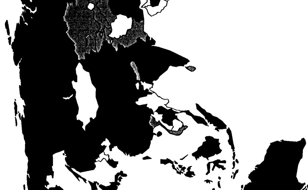
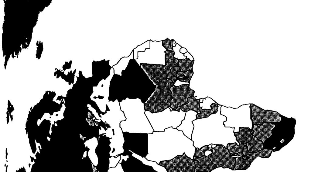
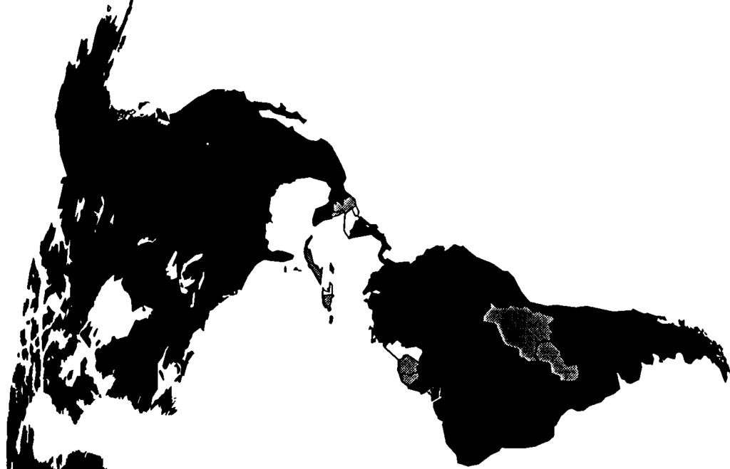
65 m.- > \ 58
66 Please send corrections, information and/or comments to: Larry Landweber Computer Sciences Dept. University of Wisconsin - Madison 1210 W. Dayton St. Madison, WI lhl@cs.wise.edu FAX INTERNATIONAL CONNECTIVITY Version 11- July 11,1994 Include details, e.g., on connections, sites, contacts, protocols, etc. Thanks to the many people from around the world who have provided information. Ilk version (postscript, ditroff, text forms, maps in postscript) and earlier versions may also be obtained by anonymous ftp from ftp.cs.wise.edu in the connectivity_table directory. In the following, BITNET is used generically to refer to BITNET plus similar networks around the world (e.g., EARN, NET- NORTH, GULFNET, etc.). SUMMARY NUMBER OF ENTITIES WITH INTERNATIONAL NETWORK CONNECTIVITY= 152 NUMBER OF ENTITIES WITHOUT international NETWORK CONNECTIVITY = 86 BITNET Col. 2 (Entities with international BITNET links.) b: minimal, one to five domestic BITNET sites, 18 entities B: widespread, more than five domestic BITNET sites, 34 entities 1P INTERNET Co]. 3 (Entities with international 1P Internet links.) I: = operational, accessible from entire open 1P Internet, 75 entities UUCP Col. 4 (Entities with domestic UUCP sites which are connected to the Global Multiprotocol Open Internet.) u: minimal, one to five domestic UUCP sites, 59 entities U: widespread, more than five domestic UUCP sites, 70 entities FIDONET Col. 5 (Entities with domestic FIDONET sites which are connected to the Global Multiprotocol Open Internet) fi minimal, one to five domestic FIDONET sites, 27 entities F widespread, more than five domestic FIDONET sites, 62 entities 0s1 Col. 6 (Entities with international X.400 links to domestic sites which are connczted to the Global Multiprotocol Open Internet). o: minimal, one to five domestic X.400 sites, 8 entities O: widespread, more than five domestic X.400 sites, 23 entities An entity is a geographical area that has an ISO two letter country code (ISO 3166). These country codes are included in the Table below for each entity (Cols 8-9). Note that the 1S0 codes do not always agree with the top level DNS (Domain Name) code(s) used for a particular entity. Network connections have been reported but not confirmed to Bangladesh, Jordan, and Mongolia and so are omitted from the table. Activity is underway to connect Lebanon, Guyana, and St. Vincent and the Grenadines but no definitive information has been received. Haiti has an link but it does not fit into any of the categories of the table Al? AL Afghanistan (Islamic Republic of) Albania (Republic of) -I--- DZ Algeria (People s Democratic Republic of) AS American Samoa AD Andorra (Principal ity of) AO Angola (People s Republic of) 59
67 International Connectivity - Version AI -I --- AQ --u-- AG BIUF- AR --u-- AN ---f- AW - IUFO AU BIUFO AT b-u-- AZ --u -- BS b---- BH BD --u -- Em b-uf- BY BIUFO BE --u -- Bz W --U f- BM BT --U f- BO --u -- BA --uf BW BV BIUFO BR IO BN biuf- BG --u-- 13F BI KH --u - CM BIUFO CA Cv KY CF ---- TD BIUF- CL -Iu O CN Cx cc BIu-- CO ---- m -u -- CG --u-- CK biuf - CR --u f- CI -IuFo HR --u-- Cu bi--- CY BIUF- CZ BIUFO DK DJ DM --U f- DO TF -Iu-- EC biu-- EG Sv GQ ER -IUF- EE ---f- ET FK Anguilla Antarctica Antigua and Barbuda Argentina (Argentine Republic) Armenia Aruba Australia Austria (Republic of) Azerbaijan Bahamas (Commonwealth of the) Bahrain (State of) Bangladesh (People s Republic of) Barbados Belarus Belgium (Kingdom of) Belize Benin (People s Republic of) Bermuda Bhutan (Kingdom of) Bolivia (Republic of) Bosnia-Herzegovina Botswana (Republic of) Bouvet Island Brazil (Federative Republic of) British Indian Ocean Territory Brunei Darussalam Bulgaria (Republic of) Burkina Faso (formerly Upper Volta) Burundi (Republic of) Cambodia Cameroon (Republic of) Canada Cape Verde (Republic of) Cayman Islands Central African Republic Chad (Republic of) Chile (Republic of) China (People s Republic of) Christmas Island (Indian Ocean) Cocos (Keeling) Islands Colombia (Republic of) Comoros (Islamic Federal Republic of the) Congo (Republic of the) Cook Islands Costa Rica (Republic of) Cote d Ivoire (Republic of) Croatia Cuba (Republic of) Cyprus (Republic of) Czech Republic Denmark (Kingdom of) Djibouti (Republic of) Dominica (Commonwealth of) Dominican Republic East Timor Ecuador (Republic of) Egypt (Arab Republic of) El Salvador (Republic of) Equatorial Guinea (Republic of) Eritrea Estonia (Republic of) Ethiopia (People s Democratic Republic of) Falkland Islands (Malvinas) 60
68 International Connectivity - Version 11 --u-- Fo -Iu -- FJ BIUFO FI BIUFO FR --u-- GF --u -- PF TF GA GM --UF- GE BIUFO DE --uf- GH GI BIUFO GR -I-f- GL --u - GD b-uf - GP -I-F- GU --u -- GT GN GW GY HT ---- HM HN BI-F- HK BIUFO HU -IUFO IS biufo IN -IuF- ID b---- IR IQ BIUFO IE BIUF- IL BIUFO IT -u -- JM BIUF- JP JO --UF- KZ ---f- KE --u-- KI KP BIUFO KR -I --- KW --U-- KG LA -IUF- LV LB --u-- LS LR LY -I-f- LI IUFO LT biufo LU -I F- MO -u-- MK --u -- MG ---f- Mw biuf- MY Mv --U-- ML --u -- MT MH Faroe Islands Fiji (Republic of) Finland (Republic of) France (French Republic) French Guiana French Polynesia French Southern Territories Gabon (Gabonese Republic) Gambia (Republic of the) Georgia (Republic of) Germany (Federal Republic of) Ghana (Republic of ) Gibraltar Greece (Hellenic Republic) Greenland Grenada Guadaloupe (French Department of) Guam Guatemala (Republic of) Guinea (Republic of) Guinea-Bissau (Republic of Guyana (Republic of) Haiti (Republic of) Heard and McDonald Islands Honduras (Republic of) Hong Kong Hungary (Republic of) Iceland (Republic of) India (Republic of) Indonesia (Republic of) Iran (Islamic Republic of) Iraq (Republic of) Ireland Israel (State of) Italy (Italian Republic) Jamaica Japan Jo;dan (Hashemite Kingdom of) Kazakhstan Kenya (Republic of) Kiribati (Republic of) Korea (Democratic People s Republic of) Korea (Republic of ) Kuwait (State of) Kyrgyz Republic Lao People s Democratic Republic Latvia (Republic of) Lebanon (Lebanese Repub: ic) Lesotho (Kingdom of) Liberia (Republic of) Libyan Arab Jamahiriya Liechtenstein (Principa: ity of) Lithuania Luxembourg (Grand Duchy of) Macau (Ao-me n) Macedonia (Former Yugoslav Republic of) Madagascar (Democratic Republic of) Malawi (Republic of) Malaysia Maldives (Republic of) Mali (Republic of) Malta (Republic of) Marshall Islands (Republic of the) 61
69 International Connectivity - Version MQ MR uf Mu YT BIuF MK FM --uf- MD MC MN Ms MA --U f- MZ MM --Uf - NA NR u NP BIUFO NL --u- AN NT --U-- NC -IUF- NZ - Iu - NI -u-- NE ---f- NG --u-- NW NF MP BIUFO NO OM --U-- PK Pw biuf- PA u PG u p y -IUf - PE - IuF PH PN BIUF- PL biufo PT biuf- PR QA -Iu-- RE EKIuf- RO BIUF- RU RW SH - -- KN --u-- LC PM Vc --u-- Ws SM ST B---- SA --U f- SN - u-- Sc SL BIuF SG biuf- SK -IUFO S1 --u-- SB so - IUFO 2A Martinique (French Department of) Mauritania (Islamic Republic of) Mauritius Mayo t te Mexico (United Mexican States) Micronesia (Federated States of) Moldova (Republic of) Monaco (Principality of) Mongolia Montserrat Morocco (Kingdom of) Mozambique (People s Republic of) Myanmar (Union of) Namibia (Republic of) Nauru (Republic of) Nepal (Kingdom of) Netherlands (Kingdom of the) Netherlands Antilles Neutral Zone (between Saudi Arabia and Iraq) New Caledonia New Zealand Nicaragua (Republic of) Niger (Republic of the) Nigeria (Federal Republic of) Niue Norfolk Island Northern Mariana Islands (Commonwealth of the) Norway (Kingdom of) Oman (Sultanate of) Pakistan (Islamic Republic of) Palau (Republic of) Panama (Republic of) Papua New Guinea Paraguay (Republic of) Peru (Republic of) Philippines (Republic of the) Pitcairn Poland (Republic of) Portugal (Portuguese Republic) Puerto Rico Qatar (State of) Re union (French Department of) Romania Russian Federation Rwanda (Rwandese Republic) Saint Helena Saint Kitts and Nevis Saint Lucia Saint Pierre and Miquelon (French Department of) Saint Vincent and the Grenadines Samoa (Independent State of) San Marino (Republic of) Sao Tome and Principe (Democratic Republic of) Saudi Arabia (Kingdom of) Senegal (Republic of) Seychelles (Republic of) Sierra Leone (Republic of) Singapore (Republic of) Slovakia Slovenia Solomon Islands Somalia (Somali Democratic Republic) South Africa (Republic of) 62
70 International Connectivity - Version 11 BIUFO ES --U-- LK SD --u - SR -I --- SJ --u- Sz BIUFO SE BIUFO CH SY BIuF- TW -u - TJ ---f- T z IUF TH -u - TG TX --u-- TO --u-- TT biufo TN BI-F- TR --u - TM TC TV ---F- UG -IUF- UA AE biufo GB BIUFO US -- - UM -IUF- UY --UF- UZ - u w VA -IU-- VE --u VN VG ---f- VI WF EH YE --uf Yu ZR ---f- ZM - uf - Zw Spain (Kingdom of) Sri Lanka (Democratic Socialist Republic of) Sudan (Democratic Republic of the) Suriname (Republic of) Svalbard and Jan Mayen Islands Swaziland (Kingdom of) Sweden (Kingdom of) Switzerland (Swiss Confederation) Syria (Syrian Arab Republic) Taiwan, Province of China Tajikistan Tanzania (United Republic of) Thailand (Kingdom of) Togo (Togolese Republic) Tokelau Tonga (Kingdom of) Trinidad and Tobago (Republic of) Tunisia Turkey (Republic of) Turkmenistan Turks and Caicos Islands Tuvalu Uganda (Republic of) Ukraine United Arab Emirates United Kingdom (United Kingdom of Great Britain and Northern Ireland) United States (United States of America) United States Minor Outlying Islands Uruguay (Eastern Republic of) Uzbekistan Vanuatu (Republic of, formerly New Hebrides) Vatican City State (Holy See) Venezuela (Republic of) Vietnam (Socialist Republic of) Virgin Islands (British) Virgin Islands (U.S.) Wallis and Futuna Islands Western Sahara Yemen (Republic of) Yugoslavia (Socialist Federal Republic of) Zaire (Republic of) Zambia (Republic of) zimbabwe (Republic of) Copyright 1994 Lawrence H. Landweber and the Internet Society. Unlimited permission to copy or use is hereby granted subject to inclusion of this copyright notice. 63
71 P OSITION P APER 3 APPENDIX B Carey E. Nell, chair QC Program. A program, called QC, has been developed by UNAVCO that will check observation data and generate various statistics on the data. W. Gurtner recommends that all operational data centers run this program as part of their automated data processing procedures. Versions of the QC program have been written and tested for various platforms (UNIX, VMS, PC). Some data centers expressed concerns with running the QC program itself, preferring instead to modify their existing software to produce the desired results. The QC program produces an output file as shown in the attachment. This file has the same naming convention as the observation (0) and navigation (N) files, e.g., ssssdddv.yys, where ssss is the site name, ddd is the day of year, v is the file sequence number, and yy is the year. The idea is to have the QC program executed as close to the data as possible, i.e., immediately after converting the raw data to RINEX. This procedure will help to ensure that only complete data files are transmitted to the regional and global data center levels. The QC program can also be used as an operational tool on a daily basis to peruse the health of the IGS network, New GPS data producers can be encouraged to utilize this program from the start. Review of Data Transmission. P. Morgan suggested that in light of the inclusion of the QC output file with the transmission of the daily observation and navigation files, a new way to transmit data may be in order. He suggested that the IGS may want to adopt a packaging program, such as TAR or ZIP, that would concatenate and compress the observation, navigation, and summary files into a single file. The regional or global data center would then break apart these files for use by the user community. If the S file is placed as the last file in the package, the regional or global data center can verify that a complete transmission occurred by perusing and verifying the contents of the S file. Options for a new data transmission method, as well the QC program, will be studied by the Communications Working Group (P. Morgan, W. Gurtner, K, Stark, C. Nell, and J. Kouba); recommendations will be made to the IGS Governing Board by July Implementing Data Flow for New Sites. The IGS needs to define the data flow for a new station coming on-line, prior to operation if possible. Often data centers see new sites showing up, without prior arrangements being made for the disposition of the data, The goal in defining a data flow is to minimize the traffic on the Internet and the redundant transmission of data. This topic is closely coupled with the classification of stations in the IGS Network (e.g., global, regional, registered). Obviously, global sites need to be available at the global data center where regional or registered sites do not. However, how and when are new sites classified? One suggestion was to have the Analysis Coordinator poll all Analysis Centers to ascertain their interest in analyzing data from a new site. The important item here is that the IGS Central Bureau must be informed of new sites as soon as possible, before they are ready to transmit data, and must then inform the Analysis Coordinator. Finally, after recommendations by the AC, the Central Bureau should inform all data centers of the new site and its designated data flow path. Core Sites. The Analysis Centers recommended that the number of core sites to be used for routine orbit production be increased from thirteen to at least fifteen. Backup and redundant sites should also be identified, perhaps collocated with SLR or VLBI, but the coordinates of these sites should not be held fixed. 65
72 IGS Reports. I. Mueller stated that the IGS Reports produced by the Analysis Centers are quite useful and encouraged NGS to begin routine weekly submission of these reports. M. Schenewerk will relay this message to his colleagues at NGS. Proposed New IGS Products. The new products proposed in Position Paper 2, covariance matrices and IGS site coordinates, should not pose a burden on the Global Data Centers. These files will not be larger than the orbit files now produced by the Analysis Centers. Sampling Rate. Questions arose about increasing or decreasing the sampling rate of receivers in the IGS network. Are users requesting a higher sampling rate, or should the IGS lower the sampling rate in order to save data transmission costs? W. Gurtner reports that the Zirnmerwald receiver samples data at one second; users requesting these data can obtain the data. For the IGS, the Zimmerwald data is decimated to thirty seconds; the undecimated data are then discarded. Other receiver agencies may adopt similar policies, but for now, no IGSwide change in sampling rate was recommended. RINEX Originator. W. Prescott wanted to publicly commend the efforts of W. Gurtner and company in the design and maintenance of RINEX. He believes that without such a coordinated effort and standard, universally recognized format, the IGS could not have become the successful service that it now is. This recommendation was followed by a round of applause for Werner. Figure 1 Rinex Header 2 OBSERVATION DATA G (GPS) RINEX VERSION / TYPE TRRINEXO V2.4.7 VM AIUB 22-Nov-94 09:24 PGM/RUN BY/DATE BIT 2 OF LLI (+4) FLAGS DATA COLLECTED UNDER AS CONDITION COMMEN1 Z IMM MARKER NAME OBSERVER / AGENCY 2691 TRIMBLB 4000SSE 5.68 REC#/TYPE/VERS o 4000ST L1/L2 GEOD AIW #/TYPE APPROX POSITION XYZ AWIWNNA: DELTA H/E/N 1 1 WAVELENGTH FACT L1 / 2 5 Cl L1 L2 P2 P1 # / TYPES OF OBSERV 30 INTERVAL TINE OF FIRST OBS END OF HEADER END OF HEADER 66
73 Figure 2 QC Program Output QC V3 by UNAVCO StmuMry File: U:[WORK]ZIMM S Receiver type: trimble 4000sse s II -##########I+ 1###########+ I A 21 ###############+ 1######+ T 41##++ 1#####-1+ 1############1,E 51 +###################+ I L 61.##################+ L 71 ###########+ 1###########++ I 91 #I#################I+ T 12] *******************++ E 141 ###################+ I 15 I.##################++ I 161#############+ 1####+ 1#1 I 17 I +####1+ 1###############+ I 181#####+ 1############# I 19J######### #######1 201 ###################++, 211 +##11##++ I###############P I 22 I #################I I 23 I ##########+ 1############+ I 241#####+ 1##########+ +1####### #############++ 1#######+ 261 ##################+ I 271*************+ I**** I 281 1#################++ 291#+ S###############I I 311 ##################+ I CLKICCC CCCCCCCCCCCCCCC cc Ccccccccccccccc ccc Cccc cccl l l l l l l l :01 23:59 Time of First Epoch in File (year,month,day,hour) : : 1 Time of Last Epoch in File (year,month,day,hour) : :59 Observation Interval for File (in seconds) 30 Elevation cutoff for qc 10 Total number of observations expected Total number of observations in file Total number of points deleted 824 Data collection percentage 93 RINEX vs qc point pos cliff [l(m] 0.04 Average MP1 : Average MP2 : # of points for MP moving average 50 Average clock drift [msec/hrl Average time between resets [rein] : Number of detected slips 85 Observations per slip 232 first epoch last epoch hrs dt #expt #have % mpl mp2 Olslp SUM : : Meaning of flags: I slip detected on iono phase S multipath slip MP1 andmp2 R multipath slip on MPl only P multipath slip on MP2 only C clock reset / slip (optional) G gap in data - SV up but no data found + sv data but below elev mask Ll C/A only no AIS # L1 CIA only A/S : LI P only no A/S. L1 P only A/S - LI C/A L2 P no A/S i LI C/AL2 PAIS * L1 P L2 P no AIS YLlPL2PA/s 67
74 P OSITION P APER 4 t) ENSIFICATION OF THE ITRF THROUGH FIEGICINAL. G PS N ETWORKS: ORGANIZATIONAL A$W ECTS Gerhard Bculler (Astronomical Institute, LJnivcrsi(y of Berm, Switzerland) Jan Kouba (Natural Resources, Caiiada) Ruth E. Ncilan (Jet Propulsion Laboratory, IJSA) Abstract Today, after only two years of operation, the coordinate series produced by the Analysis Centers of the International GPS Service for Geodynamics (IGS) are valuable contributions for the realization of the L5RS Terrestrial Reference Frame. The consistency and the precision achieved in the analyses of the existing IGS network are already comparable to the results of the other space techniques. Also, the costs for the user equipment (not of the. space segment (!)) are much lower than in the case of VLB1 and SLR, Should the IGS be successful to de~sifi the:itrf through regional,gps networks, there can be little doubt that the GPS will bi a ve~ powerful contributor to the future, realization of the X I RF, and that it will play the key role, when making the ITRF accessible to a growing user communily. The present final version of Position Paper 4 (in a series of four papers prepared for the IGS workshop Densification of the ITRF through Regional GPS Networks) was modified in order to take into account the conclusions from the other position papers and the discussions and decisions of the December 1994 workshop. In any case, such a densification has to be based on the experiences gained during two years of IGS operations. Moreover one has to consider that the IERS is responsible for the establishment of the ITRF, the IGS Central Bureau acts as the GPS coordinator for the IERS, in particular the IGS coordinates the GPS contribution to the IERS, in many geographic areas there already exist regional organizations which are responsible for the realization and maintenance of the reference frame in this specific region. In section 1 we review the development of the IGS. In particular we look at the impact of the terrestrial reference frame(s) on the IGS products generated on a daily basis (orbits and Earth rotation parameters). We summarize the improvements (concerning the coordinates of the tracking network) emerging from the experiences gained during two years of IGS processing. In section 2 we review the IGS terms of reference to remind ourselves of the IGS responsibilities before anal yzing the implications of different network densities and discussing the organizational implications. In section 3 we summarize the principles to be observed for a densification and we summarize the action items from the organizational point of view. I EXPERIENCES BASED ON TWO Y EARS OF IGS OPERATIONS The 1992 IGS Test Campaign started on 21 June 1992, and ended on 23 September The receivers of the global IGS network were not turned off in September 1992 and the IGS Analysis C,enters continued to turn out their results as well. The IGS Oversight Committee decided in October 1992 to formally establish the IGS Pile? Service, which started on 1 November It ended on 31 December 1993, yielding its place to the official IGS that started on 1 January
75 During the 1992 IGS test campaign a two weeks interval around August 1 was reserved for the so-called Epoch 92 campaign. The purpose of the campaign actually was a first densification of the Global Network. Although there were interesting results in particular regions or of particular analyses, the main purpose, a general densification of the network, could not be achieved. We learned from this experiment that the organizational and the logistic aspects of a densification based on a campaign-type GPS experiment are extremely difficult to handle. One possible conclusion is to use permanent tracking sites only for the purpose of densification. The 1992 IGS test campaign, Epoch 92, and the IGS Pilot Service are documented [Beutler and Brockmann, 1993]. Let us analyze the Global IGS Operations between June 1992 and December It was extremely important and helpful that the IGS series of earth rotation parameters were continuously analyzed by the IERS (Rapid Service Subbureau and IERS Central Bureau). These weekly resp. monthly analyses published in the IGS-report-series helped to reveal inconsistencies in the results of the IGS Analysis Centers. The impact of the actual realization of the terrestrial reference frame became obvious when the seven IGS Analysis Centers started using the ITRF 92 [Boucher, et al., 1993a] instead of the ITRF 91 on January 1, 1994, and, when (at the same time) they started fixing (or heavily constraining) essentially the same set of station coordinates using the same information for the local ties. Figure 1, extracted from the weekly IGS-reports of the IERS Rapid Service Subbureau, shows the offsets of the IGS Analvsis Centers Dole estimates relative to the IERS Ra~id Service Subbureau s solution (whi~h is based on ~ combination of VLBI, SLR, and GPS)~ ERP x- Cornpo~t, Referen@= NEOS (Rapid) Pole ERP y-component, Reference= NEOS (Rapid) Pole B E <!- 0 =() II II.* -1 ; z iil -2 h aaol 4S8CKI 49xxl 49Xxl 4e400 4e000 49s00 48a00 4% C0 4efxxl 49aco MJD MJD * CODE * EMR w ESOC x GFZ * CODE H EMR + ESOC w GFZ - JPL H NOAA * Slo I - JPL * NOAA - Slo I Figure 1 Development of the monthly means of the earth rotation parameters x and y of the IGS Analysis Centers relative to the IERS Rapid Service Subbureau. Clearly the consistency of the individual IGS series but also the consistency between the series became much better after January 1, 1994 (MJD=49 353): The differences between the individual series were reduced from more than 3 mas to less than 1 mas in the x- and y- estimates of the pole. The conclusion is thus clear: the terrestrial reference frame is of greatest importance for the computation of the earth rotation parameters, the consistency of different series is in principle dictated by the quality of the terrestrial network. 70
76 too MJD CODE E M R ESOC e99 JPL - NGS - SIo - G F Z Figure 2 Development of the orbit quality of the IGS Analysis Centers between September 1992 and December 1993 based on the Orbit Comparisons through 7 parameter Helmert transformations. It was a serious problem that at the beginning of the IGS activities in Summer 1992 the orbits were not regularly compared. The situation was considerably improved during the IGS Pilot Service, when the Analysis Center Coordinator started comparing the daily orbit files through similarity transformations. During this phase the orbit consistency came down from the 1 m 50 cm level roughly to the 20 cm level (after taking out the rotations between the series). This development may be seen in Figure 2, where the orbit quality of the individual solutions is shown between June 1992 and December The quality of the individual series was estimated from the rms errors of the 7 parameter Helmert transformations between all possible pairs of daily solutions (SP3 files delivered to the IGS Global Data Centers). The analyses, published every week in the IGS-report-series, were stimulating indeed. They were to a high degree responsible for the quality improvement of the individual series. The results underlying Figure 2 also were responsible for the development of the combined IGS orbit: the consistency achieved made it clear that (after transformation to a common reference) a combined orbit would make sense and that outliers of individual centers could easily be removed. At the 1993 IGS Analysis Center Workshop in Ottawa it was therefore decided that the main duty of the new Analysis Center Coordinator would be the production of a combined, oflicial IGS orbit [Beutler, et al., 1994]. 11 Today we are looking back at about one year of orbit combination. Figures 3 and 4 show that the consistency of the individual orbit series, documented by the (weighted) rms error relative to the combined IGS orbit, again could be improved. At the end of 1994 the combined IGS orbit and the best individual series have a quality of about 10 cm rms per satellite coordinate. 1 1 See also Kouba [1993]. 71


77 ri.--rrw-w r Day of Year 1994 ;/ _ f,,: Analysis Ger)t&( ~ C O D o@ EtvW m ESA we GFZ +-t+ JPL I _+* NGS M$7f SK) ,,., 3J, F@,iIT 3 Ih@o~mei~t of the orbit Quality of lhi IGS Analysis Centers between November 1993 and November 1994 based on the Orbit Combination produced by the IGS Analysis Center Coordinator. All orbits includecl. We conclude that orbits and earlh rotation parameters are in excellent shape mainly because regular controls and compar-isons were performed. We have seen that after a while the consistency of the orbits was such that h combined IGS o~bi~ cduld be pro@lced. This combined orbit is ti blessing for the user community, which no longer has to make the distinction between individual series. It is a blessing fo~.the IGS Analysis Centers as well, because every center may claim to contribute iti the appropriate way to one and the same official 1(3S product. We might conclude from Figure 1 that a similar procedure, i.e. the production of a combined IGS pole, would make sense for the polar motion, too. Such a combined IGS pole might ea sil y be produced together with the ICJS tirbits. 4 ~ To a cxxtain degree a similar development as in thti case of orbits and earth rotatiort parameters may Im observed for the satellite (tind potential y the receiver) clocks, too. The production of combined ICX clock corrections is very stimulating for those centers basing their analysis on the zero-difference observable. It would not be. amazing if the other centers would start ~ro(]ll~ing clock, information, too, in the near future. Such developments show that the screening-, comparing-, and combination-processes are the keys to improve the ]GS products. 72

78 ~5j_.....i A *.. i * r.-. 1 ;-:,,: ( -j..:.,.: G C:; i 3
79 sense to compare directly the coordinates as they are routinely turned out every day by all IGS Analysis Centers. Station n-s e-w UD Transformation (a) GRAZ 11 OO1MOO2 HERS 13212MO07 KOSG 13504M003 MADR 13407S012 MATE 12734MO08 TROM 10302MOO3 WETT 14201MO09 ZIMM 14001M004 ONSA 10402MOO4 METS 10503S011 NYAL 10317MOO1 MASP 31303M001 JOZE 12204MO rms for trafo ~a~ 0,0016 0,0015 0,0044 Transformation (b) G~Z 11OO1MOO HERS 13212MO KOSG 13504M MADR 13407s MATE 12734MO TROM 10302MOO WETT 14201MO ZIMM 14001MO ONSA 10402MOO METS 10503S NYAL 10317MOO rms for tra fo [b) 0, Transformation (c) GRAZ 11OO1MOO HERS 13212MO KOSG 13504MO ,0000 MADR 13407s MATE 12734MO TROM 10302MOO WETT 14201MO ZIMM 14001M ONSA 10402MOO Z6 METS 10503S NYAL 10317MOO MASP 31303MO JOZE 12204MO ms for trafo {c) Table 1 Residuals in meters of seven parameter Helmert transformations between the European partof the IGSsubnetas computed bythe CODE Analysis Center (using the nine first months of1994) and (a)theeuropean part ofthe IGS subnet ofstations ascomputed by CODE (using the last nine last months of 1993), (b) the ITRF 92, (c) the ITRF
80 In view of the consistency the IGS reached in the domains of the pole, orbits, and clocks we have to ask ourselves whether the procedure set up for the coordinates is satisfactory. By comparing GPS solutions made by one and the same agency but stemming from different time periods (e.g., from different months) we know that the GPS- and agency- internal consistency is of the order of a few millimeters per coordinate, whereas differences on the centimeter level still exist between the GPS solutions and the official ITRF coordinates. This fact is documented in Table 1 where we see that the residuals of a seven-parameter Helmert transformation between two nine-month GPS solutions are substantially smaller than the residuals corresponding to the transformation between the 1994 GPS solution and either the ITRF 92 coordinates [Boucher, et al., 1993a] or ITRF 93 coordinates [Boucher, et al., 1993b]. That the ITRF 93 is clearly superior to the ITRF 92 (and that the coordinate updating process converges) follows by comparing the residuals of transformations (b) and (c)in Table 1. This fact also documents that the GPS starts playing a very important role in the process of defining the more recent (and the future) versions of the ITRF. On the other hand Table 1 also illustrates that we are still suffering from reference frame inconsistencies in the broadest sense. Most of these inconsistencies have nothing to do with the IERS producing these coordinate sets, but with GPS internal inconsistencies and with inconsistencies between the GPS and the other space techniques. Today we do not know e.g. for sure whether all the IGS Analysis Centers are actually using the same information concerning the local ties. Most of the problems might easily be removed by performing at regular intervals (e.g., each week or each month) transformations between free coordinate solutions of all centers. In a first step we would find out which coordinates (center coordinates, GPS eccenters) are used by different agencies. We would also quickly find out about antenna eccentricity problems between different centers. There can be little doubt that such a procedure would lead to a comparable improvement in coordinate consistency as in the case of orbits and Earth rotation parameters. Let us therefore draw the following conclusions: In order to improve the consistency of all IGS products and independent on the degree of densification agreed upon it would be highly desirable to establish a regular (e.g., weekly) coordinate comparison service. The coordinates and the associated variance-covariance matrices of free adjustments as delivered by the Analysis Centers should in a first step be compared through transformations. Discrepancies (point id s, antenna heights, epoch of the coordinates, etc.) should be removed, and the results regularly summarized in IGS-reports. If a degree of coordinate consistency comparable to that of the orbits and of the Earth rotation parameters is reached, the same free network solutions may be used to produce combined IGS coordinate sets. c Such combined coordinate sets should not replace the submitting of the individual series to the IERS neither the production of the ITRF by the IERS. It would guarantee that the individual series going into the official ITRF solutions are much more consistent than they are now. Combined, official set of IGS coordinates would play a similar role for the user community as the combined orbits. User-friendliness is an important aspect, too. 75
81 II DENSIFICATION OF THE IGS NETWORK IN V IEW OF THE IGS R ESPONSIBILITIES In this section we first extract the essential parts concerning a densification of the existing IGS network from the terms of reference (section 2.1). In section 2.2 we briefly discuss two extreme cases for a network densification considered to be realistic at present. In section 2.3 we discuss the organizational aspects as a function of the network density. The network densification in view of the IGS terms of reference The IGS terms o~re~erence [IGS Central Bureau, 1994] state that the primary goal of the IGS is to provide a service to support, through GPS data products, geodetic and geophysical research activities. the IGS collects, archives and distributes GPS observation data sets of sufficient accuracy to satisfy the objectives of a wide range of applications and experimentation. These data sets are used by the IGS to generate the following data products: - high accuracy GPS satellite ephemerides - Earth rotation parameters - coordinates and velocities of the IGS tracking stations - GPS satellite and tracking station clock information - ionospheric information the accuracies of these products are sufficient to support current scientific objectives including realization of global accessibility to and the improvement of the International Terrestrial Reference Frame (ITRF) - monitoring deformations of the solid Earth - monitoring Earth rotation - monitoring variations in the liquid Earth - scientific satellite orbit determination - ionosphere monitoring The IGS accomplishes its mission through the following components: - network of tracking stations - data centers - Analysis and Associate Analysis Centers - Analysis Coordinator - Central Bureau - Governing Board the Network of tracking stations consists of Core Stations and Fiducial Stations. The core stations provide continuous tracking for the primary purposes of computing satellite ephemerides. - the fiducial stations may be occupied intermittently and repeatedly at certain epochs for the purposes of extending the terrestrial reference frame to all parts of the globe and to monitor the deformation of a polyhedron (designated as the IGS polyhedron) defined by Core and Fiducial Stations located at the vertices. 76
82 All considerations concerning the densification of the IGS network (called Core network above) have to be based on the extract of the terms of reference reproduced above. Naturally we have to take into account the experiences gained during the last two years. The primary goal of the densification of the IGS network undoubtedly is the realization of global accessibility to and the improvement of the IERS Terrestrial Reference Frame. This leads immediately to the question of the required network density. Let us deal with the two aspects separately: The improvement of the ITRF is going beyond the GPS as a technique. The IERS is responsible for this part. For the other aspect, the global accessibility, the IGS is responsible, at least where GPS is concerned. We need to know whether (a) 3000 km, (b) 2000 km, (c) 1000 km (d) 500 km spacing between the sites of the IGS network is sufficient for regional GPS networks. In the next section we will see that only the spacings (a) and (b) are realistic. The number of sites in the future IGS Network The following considerations are meant to fix the order of magnitude for the densification, only. The aspect of receiver spacing was considered in detail in Position Paper 1 (Zumberge et al., 1995), where a special measure (the ~-measure) was introduced to describe the quality of a global geodetic network, The distribution of the sites on the globe should be as regular as possible. We are reminded that the vertices of regular polyhedra are optimal for that purpose [Mueller, 1993]. In order to get an impression of the orders of magnitude we use the icosahedron (consisting off= 20 triangles (faces), v = 12 vertices, e = 30 edges) as a starting point for our discussions. The length 1 of the edges of an icosahedron with its vertices on the surface of the Earth is 1 = 6700 km. Undoubtedly a polyhedron of 12 vertices is not a good candidate for the IGS polyhedron. Let us therefore partition each of the equilateral triangles of the icosahedron into four congruent equilateral triangles. Projecting the resulting v = 30 new vertices (one on each edge of the icosahedron) onto the surface of the sphere (central projection) and adding them to the original 12 vertices we obtain a new polyhedron consisting of f = 4. f (almost) equilateral triangles, v = v + e = 42 vertices, and e = 20 e + 3 s f = 120 edges. This new polyhedron is not regular (either five or six edges meet in the vertices, the edges are not all of equal length). The differences in the lengths of the edges are not important for our purpose, however. This new polyhedron with v = 42 vertices is an interesting candidate to play the role of the IGS polyhedron: the edges length of about 1 = 3500 km is sufficient to guarantee a substantial number of interferometric observations relative to the neighboring receivers. A receiver brought to an arbitrary point of the Earth would not be farther away than about 2000 km from the nearest IGS sites. This is a distance which allows a relative positioning with the GPS within the centimeter in all coordinates within a few days. The number of vertices (42) is not.frightening. It is the order of magnitude which is handled today by the IGS Data Centefi and Analysis Centers. We m;y thus conclude that the IGS would have no problems handling such a minimum solution with the existing structure already. This minimum IGS network is closely related to what is called a core network in the IGS terms of reference. It is a subset of the network which is analyzed by the IGS Analysis Centers. 77
83 Let us go one step beyond this minimum polyhedron. If we partition each triangle of our minimum IGS network in the same way as we did it with the icosahedron and if we project the new vertices on the surface of the Earth, we again obtain a new relatively regular polyhedron consisting of triangles only. This polyhedron has v = 162 vertices, e = 480 edges, and f = 320 faces. This new network has a spacing between receivers of about 2000 km. The lengths of the baselines would not pose major problems to the user of the IGS: Most baselines we are dealing with today in the global analyses are at least of this length. The big advantage of the new network is the improved accessibility to the ITRF: A receiver at an arbitrary point of the Earth s surface would be at maximum at 1000 km from the nearest IGS site(s), and 1000 km baselines are easily handled today even with relatively modest software packages. The next partition of the polyhedron (leading to a spatial separation of the IGS sites of about 1000 km) would already result in a polyhedron with 542 vertices, a number which is beyond the scope of present capabilities. At present we therefore consider a polyhedron with v = vertices as the maximum size for IGS network. This maximum number takes into account that a certain degree of redundancy is necessary and that there is a demand for a higher density in some parts of the world (e.g., North America and Europe). Terminology and Organizational Aspects of the Densification At the workshop and at the IGS Governing Board (GB) meeting following the workshop (December 6, 1994 in San Francisco) the issue of terminology for the IGS network and the IGS stations was discussed. It was felt that the terminology used in the terms of reference, i.e. the terms Core Station and Fiducial Station should be changed and simplified. Let us try to summarize the result of these discussions: For IGS external use only the term IGS Station is relevant. It is not necessary to make the distinction between two types (e.g., Core and FiduciaZ) for the outside world. It is important for the user of IGS products, however, that precise and reliable ZTRF coordinates and velocities are available for this site and that tracking data may be retrieved (with an acceptable delay) for this site for any given epoch. The set of IGS Stations forms the IGS network. The distinction between two types of stations, i.e. Global and Regional IGS sites, may be needed and used internally within IGS in regards to operational and technical considerations. The IGS (Associate) Analysis Centers producing free network solutions are e.g. requested to include at least three IGS Stations which were in turn included over a long time period in several solution series of IGS analysis centers (such stations were labeled Global in Position Paper 2 (Blewitt et al., 1995)). Also there are consequences for the data management: Only the data of the latter station type have to be stored by the IGS Global Data Centers, the data of the regional sites are handled by regional centers. The information where the data for an IGS Regional Station is available must be stored in the CB Information System and is thus easily accessible for all IGS users. However, all the IGS stations must be conforming to the same IGS standards and provide users with equally precise access to the ITRF. The above definition assumes that every IGS station is analyzed by at least one IGS (Associate) Analysis Center. This implies that, if a candidate IGS station is coming up, the Central Bureau will poll the IGS (Associate) Analysis Centers as to their intent on using the data of the new 78
84 station in their solutions. If at least one (A)AC will process the data on a routine (daily) basis the station is considered an IGS Regional Station and is asked to forward the data to the nearest regional data centers. If the station turns out to be used by a certain number of ACS, the regional data center are asked to forward the data of the candidate IGS site to the Global Data Center(s). If no IGS (Associate) Analysis Center will process the data of the candidate station, the station cannot be considered as an IGS station. It was discussed at length whether or not it is necessary to specify a minimum distance to the closest existing IGS site for a new station coming up. Most of the attendants of the workshop and most GB members know that such a minimum distance would make sense: there is obviously no point of establishing new stations at a distance of only a few tens of kilometers of existing sites. On the other hand the only drawback of not specifying such a minimum distance consists of a possibly irregular spacing between stations. This probably is of little interest to the IGS user, on the other hand: he is interested to include as many IGS sites with precise and reliable coordinates and velocities as possible into his regionalflocal analysis. The problem of unnecessary data transfer should be dealt with, because the data of IGS Regional Sites are no longer flowing up to the Global Level. We believe that at present the structure of the task outlined above is sufficient. It may be necessary in future to add a third level of IGS stations, which might be called a local level. The only difference of such IGS Local Sites as compared to IGS Regional or Global Sites would be the location of the data. If reliable and precise coordinates are available in addition to the station s tracking data in a data center below the regional level (and the user again finds this information in the CBIS) such a station may be used in very much the same way as Regional and Global IGS sites. This hierarchical concept will work, provided we manage to structure the dataflow as outlined above. Let us conclude this section with a few remarks concerning the next steps of the densification process: The existing IGS Network of about 60 stations is far from its ideal shape. There must be a high priority given to filling in the gaps (southern hemisphere, Eastern Europe, Asia). Each station showing up in one of the gaps will automatically be analyzed by at least some of the (at present seven) Analysis Centers. The recommendations of position paper 1 should be followed to fill in these gaps. Only permanent tracking sites should be considered as candidates for the IGS Network. The network densification asks for frequent and regular comparisons/combinations of the coordinate solutions produced by the IGS Analysis Centers and by future Associate Analysis Centers. Such a combination, when done properly, is a major undertaking, requiring resources and continuous commitment. One or two separate organizations must take care of this task in the operational phase. Such centers will have to work closely together with the IGS Analysis Center Coordinator and the ITRF section of the IERS. The IGS densified network consisting of 100 or more stations will involve many different institutions and therefore with utmost certainty also different receiver types. The combination of different receiver/antenna types will be an important issue in future. Thus, the problem has to be addressed by the IGS in future. 79
85 c The realization of a relatively dense IGS network will be an ambitious project. It only may be successful if the interfaces with the IERS on one hand and with the regional networks on the other hand are set up carefully and in close collaboration with the corresponding organizations. Ill S UMMARY, CONCLUSIONS, ACTION ITEMS Two years of IGS operations show that frequent and regular comparisons of the results produced by the IGS Analysis Centers were and are the key for accurate and reliable products. Furthermore the official IGS orbits prove that combined products are beneficial to the user community. From such experiences one has to conclude that the coordinates produced by different IGS Analysis Centers should be checked in the same way as the orbits and the Earth rotation parameters. It was recommended at this workshop that weekly coordinate comparisons should be performed in order to reach a coordinate consistency level comparable to that of the orbits and the Earth rotation parameters. It is clear that such a coordinate comparison must be built up in close collaboration with the IERS. It was decided to use essentially the structure as proposed in Position Paper 2 (Blewitt, 1995). The following conclusion and action items concerning the coordinate comparison/combination were drawn resp. proposed at the workshop and confirmed at the Governing Board on December 6, 1994: c Workshop Conclusion No 1: One, ideally two Associate Analysis Centers shall perform weekly comparisons and combinations of the coordinate solutions of all IGS Analysis Centers and of future Associate Analysis Centers analyzing parts of the densified IGS network. As suggested by (Blewitt et al., 1995) an agency performing coordinate comparisons and combinations in the way described in position paper 2 is called an Associate Analysis Center of type-2 (AAC type-2), agencies analyzing and contributing parts of the (densified) IGS network are called Associate Analysis Centers of type-1 (AACS type-l). The following facts had to be considered when planning the action items for the implementation of the AACS of type-2: Seven IGS ACS are in principle ready to produce weekly so-called free coordinate solutions as proposed by in Position Paper 2 (Blewitt, 1995). These solutions are ready to be used by AACS type-2. In view of this favorable situation it seemed advisable to follow the suggestions made by (Blewitt, 1995) and to establish a pilot phase for AACS type-2 to last for one calendar year early in It was assumed necessary that candidates for AACS of type-2 should have a sound experience in regular IGS processing. Therefore, only a small group of individuals and agencies had to be contacted for the organization of the pilot phase for AACS type-2. The Department of Surveying of the University of Newcastle, represented at the workshop by G. Blewitt and the Institute of Geophysics and Planetary Physics of Scripps Institution of Oceanography, represented at the workshop by Y. Bock, expressed their interest to act as AACS type-2 during such a pilot phase. 80
86 The IERS is responsible for the maintenance of the ITRF. It was considered important that the ITRF section of the IERS (the IGN in Paris) would accompany the test phase of AACS type-2 by analyzing the products of AACS of type-2. Based on these considerations the following action items were agreed upon at the GB meeting following the workshop: The GB chair was asked to write letters to the seven ACS, the two institutions mentioned above, and to the University of Texas (AC during the 1992 IGS test campaigning) to ask for participation in the test phase for AACS type-2. G. Blewitt was asked to propose a specific timetable for the pilot program by the end of January 1995 (Blewitt, 1995). C. Boucher from the ITRF section (at the IGN) formally agreed to accompany the test phase of AACS type-2 by analyzing the coordinate series produced by the AACS type- 2 at regular (probably monthly) intervals. The permanent IGS tracking network was considerably growing since The number of permanent sites (about 60 today) would be sufficient to buildup what was presented in section 2 as the minimum solution for the IGS Global Network with a spacing between sites of about 3500 km. However, although the actual distribution of IGS sites was much improved since 1992, we are still far away from an ideal distribution in the sense of a regular polyhedron. The problem of obtaining the desired coverage for the IGS network was addressed in detail in Position Paper 1 (Zumberge et al., 1995). Concerning the instrumentation of future IGS sites the following conclusion was drawn: c Workshop Conclusion No. 2: lgs stations should be permanent stations wherever possible. Although near real-time data transmission is desirable, permanent receivers with less-than real-time data communications would be acceptable, too. In order to actually obtain the necessary coverage it was decided at the GB meeting to take the following action:. The CB was asked to draft a Callfor Participation (CFP) identifying regions for the IGS network densification. This CFP together with follow-up letters to agencies working in areas of special interest to the IGS are to be sent out in March The tide gauge project of IAPSO [Carter, 1994] is of special interest to the IGS to obtain the necessary coverage in the oceans (tide gauges on islands). A close cooperation between IAPSO and IGS seem to be of particular interest in this context. The densification of the IGS network leads to a considerable growth of the daily processing workload. It must be the primary goal of the IGS to avoid the situation that data are collected but not analyzed. This is why we ask that each site with an IGS label has to be included in the solution series of at least one (A)AC. It seems clear that this additional work has to be done by new IGS Associate Analysis Centers of type-1 (using the terminology in Blewitt, 1995). It was recommended at the workshop that a Call for Participation should be issued for AACS of type 1. On the other hand it seemed premature to send out such a call before having clearly defined the duties of such AACS of type-1 and before having a clear picture of the densified network. Based on these considerations the following actions were invoked at the GB meeting in December 1994: 81
87 A format working group consisting of G, Blewitt, Y. Bock, C. Boucher, W. Gurtner, and J. Kouba will come up with a Software Independent coordinate solution EXchange format, tentatively called SINEX (!). This format has to be available at the beginning of the AAC type-2 pilot phase. The expectations to an IGS AAC of type-1 are given in Position Paper 2. An extract will be included in the CFP for AACS of type- 1. The expectations to an IGS site are given in Position Paper 3 (Gurtner and Neilan, 1995). A Call For Participation for AACS type-1 will be delayed until the pilot program has had a few months of operation.. Not all the problems in the area of the densification of the IGS network could be addressed at the 1994 IGS workshop Densification of the ITRF through Regional GPS Networks. But the workshop will be remembered as the principal milestone of this ambitious project provided the actions outlined in this section are executed in a timely fashion. There can be little doubt that this will be the case. The workshop clearly documented that the innovative spirit within the IGS and the firm wish to work together in an International, truly Global Frame are still as strong as in the early days of the IGS. The workshop participants wish to thank the Jet Propulsion Laboratory and of course the Central Bureau of the IGS in particular, for hosting the 1994 IGS workshop. R EFERENCES Beuter, Gerhard and E. Brockmann, eds. Proceedings of the 1993 IGS Workshop. Druckerei der Universitat Bern, Beutler, Gerhard, J. Kouba, and T, Springer. Combining the Orbits of the IGS Analysis Centers; accepted for publication by Bulletin Geodesique, October Boucher, Claude, Z. Altamimi, and L. Duhem. IERS Technical Note 15: ITRF 92 and its Associated Velocity Field: Observatoire de Paris, 1993a. Boucher, Claude, Z. Altamimi, and L. Duhem. ITRF 93 and its Associated Velocity Field, 1993b. Carter, William E. Report of the Surrey Workshop of the IAPSO Tide Gauge Bench Mark Fixing Committee. NOAA Technical Report NOSOESO06. Geosciences Laboratory, National Ocean Service, IGS Central Bureau, lgs Colleague Directory. IGS Central Bureau, Jet Propulsion Laboratory, California Institute of Technology, Pasadena, CA, Kouba, Jan, ed. Proceedings of the IGS Analysis Center Workshop. Ottawa, Canada, October Mueller, Ivan I. The IGS Polyhedron: Fiducial Sites and their Significance: Proceedings of the 1993 IGS Workshop. Druckerei der Universitat Bern, pp
88 P OSITION P APER 4 APPENDIX Jan Kouba, chair This session consisted of two presentations. Claude Boucher described his view of cooperation and coordination between the IGS and IERS in achieving an expanded international reference frame. Jean Dickey described a proposed Crustal Deformation Bureau under consideration by the IAG. Written versions of these follow. 83
89 Claude Boucher. The Realizations of the International Terrestrial Reference System (ITRS): A Challenge for a Joint IERS / IGS Solution For more than 6years, the International Earth Rotation Service (IERS) has achieved annual realizations of the International Terrestrial Reference System (ITRS), formally recommended by the IAG and IUGG since the Vienna General Assembly in Many things have been progressively improved during these 6 years, even 10 if we consider the BIH activity since 1984 in the frame of the MERIT campaign. In addition, further important issues are coming on the floor now: the International GPS Geodynamic Service (IGS) and its plans to use regional networks for densification the official inclusion of DORIS as anew technique contributing to IERS This is a good opportunity to undertake a review and critical discussion on the work done by IERS on the Terrestrial System and to identify improvements to be realized. The IERS Central Bureau has undertaken to establish a report containing a critical analysis of the present work, as well as a set of recommendations, and to design an implementation plan within IERS (between the Central Bureau, the analysis centers and others such as IGS), in order put into practice the previous recommendations. The purpose of this present paper is to discuss specific interfaces with IGS and to see how IGS can greatly contribute to these improvements. Fundamental conce~ts One of the major tasks of the IERS is to realize the IERS Terrestrial Reference System (ITRS) using results of space techniques (SLR, LLR, VLBI, GPS, DORIS), as well as auxiliary informations, such as local surveys between co-located instruments. Such realizations are called reference frames, specifically the IERS Terrestrial Reference Frames (ITRF), which consists into: a network of instruments and/or related ground markers a set of coordinates, which can be of the following types: - position at epoch to: XO - position at epoch to and veloeity : XO, V - time series of positions: Xk For the last case, we can consider in particular: daily (d) monthly (m) quarterly (q) yearly (y) Several types of frames can be considered, depending on various options. For instance, we can consider: an individual solution, which is characterized by: - a specific technique (L, M, R, P, D) a model/software/analysis center - a raw data set (type of data, period...) - a reference system which was selected to express coordinates 84
90 a combined solution for a given technique, which combines several individual solutions of the same technique a combined solution, using individual or combined solutions for several techniques We shall note x-solution (x = L, M, R, P, D) an individual solution for the technique x, xcsolution a combined solution for x, and C-solution a combined solution, Furthermore, we shall call an I-solution any solution assumed to be expressed directly into ITRS, and with the previous typology, we shall speak of xi-, xci or CI-solutions. Furthermore, a solution will be described as a set of parameters together with their variance-covariance matrix. The parameters included in the solution can be: x: E R: s: station position/velocities EOP radiosources satellite state vector We propose to define three types of ITRF solutions to be produced by the Central Bureau: primary solutions, which will be established by using all good quality individual solutions of all techniques, providing XE parameters, and XER parameters for VLBI. The combination will be performed rigorously and provide a complete result in X, E and R parameters, as well as transformation parameters from individual terrestrial/celestial systems into ITRS/fCRS. In such a solution, coordinates will be taken as XR, V for the result, needing to select a reference epoch tr. Input solutions will be accepted as XO or (XO,V), whether to is or is not equal to tr. Full covariance will be available at least for XO,V, in order to compute rigorously X and its variance at any epoch for any station.. complete solutions, which will use all available data, including regional solutions from IGS or similar data. c time series solutions, which will use time series of station coordinates from various techniques (daily, monthly, quarterly, annual). In all these types of solutions, local surveys should be preferably used as G-solutions, i.e. set of coordinates with full covariance at a given epoch. Several such solutions can be used for one site in case of repeated surveys or partial surveys at various epochs. Status and clans of the IERS Central Bureau Up to now, the basic strategy used by IERS and previously by BIH was to compute each year a new complete solution using the data submitted by the analysis centers for the Annual report. We refer to the IERS Annual Reports and Technical Notes for further details. The most recent Solution (ITRF93) has been issued recently (see IERS TN 18). The new strategy which is proposed by IERS Central Bureau is: a) To compute a satisfactory primary solution (target ITRF95) and to keep it as a reference. b) To continue yearly submissions for IERS Annual Reports. In case of the terrestrial system, evaluation of solutions will be done. If enough new material exist, a complete solution may be produced, using also other materials. c) The publication of these complete solutions may not be done annually. Such solution will be put in the ltrs by use of the current reference solution. d) In addition, with the cooperation of some analysis centers, some time series solutions will be computed, also in ITRS through the use of the reference solution. They could be produced on a regular basis, like other operational products of IERS. 85
91 Furthermore, we consider it is very important to adopt for ITRF solutions a quality code which would be attributed using several criteria to be specified, in cooperation with analysis centers and some users. For the ITRF94 solution, we plan an intermediate stage: this will be a complete solution using X-parameters expressed in Xo, V with full covariance. Pro~osals for the IERS/IGS cootxxation about TRF The relations between IGS and IERS can be expanded for the benefit of both Services. We can summarize them by the following items: IERS to IGS ITRS is adopted by IGS IERS ERP are used by IGS global analysis centers ITRF is used by IGS global analysis centers either directly or to convert their own GPS derived frame into ITRS. IERS products will also be used by IGS regional analysis centers Up to now either annual solutions or dedicated solutions (ITRF-P solutions) were used. In the future there will be a choice. We suggest to use the reference solution (ITRF95) and not change it every year. Furthermore, the fact that full consistency between ERP and TRF is now ensured by IERS is important for IGS users. IGS to IERS (for TRF) IGS global analysis centers will contribute to primary solutions if they provide the relevant XE-matrix. A standard exchange format is proposed: ISEF (see appendix) IGS global or regional analysis centers will contribute to complete solutions with X- solutions submitted in ISEF. IGS global analysis centers may also contribute to time series solutions IERS Standard Exchamze Format (ISEF] The International Earth Rotation Service (IERS) is permanently collecting, exchanging and disseminating various data. The need to use standard formats and to document them is clear, considering: the various groups involved in IERS: stations, networks, coordinating centers, analysis centers, central bureau and sub-bureau s the user s community Therefore, a set of rules is established and published under the label IERS Standard Exchange Format (ISEF). Several versions will be considered. This document presents the ISEF. 1, dealing with the exchange of analyzed data (EOP, station positions,...). 1. Data types. Three types of data can be identified for IERS: a) raw data b) analyzed data c) auxiliary data Raw data consist into the various measurements analyzed by the IERS analysis centers or the central bureau. They are relevant to one of the techniques presently considered by IERS: SLR data LLR data VLBI data GPS data 86
92 DORIS data The necessity of standardization is under the responsibility of the IERS technique coordinator. Currently, each technique has at least one standard exchange format (ex. MERIT2 for SLR, MARK3 for VLBI, RINEX for GPS...). We should also consider local survey data as a potential other type (terrestrial or GPS). Presently, only results will be considered, in the auxiliay data type. Analyzed data are information generated by any analysis center participating to IERS, basically analysis centers for the various techniques, the central bureau and sub-bureau. This is also the type of data which are disseminated by IERS to the user s community. Auxiliary data include any data used to describe a specific solution, in particular the model used, referring to the IERS Standards. They also include station description and occupancy information, as well as local eccentricities. In summary, the various types of information handled by IERS are: A Raw data AL SLR data AM LLR data AR VLBI data AP GPS data AD DORIS data AG geodetic ground survey B Analyzed data BE EOP data (ERP, precession, nutation) BX SSC data (station positions and velocities) BC RDS data (radiosources positions) BI global analysis (combined solutions including several of the previous types, as well as covariance) C Auxiliary data Cs Model parameters CG station description and local eccentricities 2. ISEF. 1: Exchange of analyzed data. An analyzed data set will be defined as a sequence of scalar numerical parameters (xi), i= 1,N, where N is the dimension of the data vector, together with a list of labels Li a list of scalars Ck giving the variance-covariance information between the parameters. Li gives the description of the parameter Xi. Ck gives the variance-covariance information. A possible recommended procedure will be to give the matrix (correlation coefficient and standard deviations in the diagonal) corresponding to Xi, scanning the upper triangle by columns: cl = S1 C2 = corl,2 C3 = S2 C4 = corl,3 C5 = cor2,3 87
 in which the demands would be met by a network of centers (see Figure on following page).")
93 Jean Dickey With maturing space technologies (GPS and others) and the wealth of data now available, the International Association of Geodesy (IAG) is considering the formation of a Crustal Deformation Bureau (CDB) in which the demands would be met by a network of centers (see Figure on following page). Such a Bureau would be of great interest to the International GPS Service for Geodynamics (IGS) and close links would be established with it. The structure proposed parallels that of the International Earth Rotation Service (IERS). These coordinating centers are suggested based on three measurement types: classical terrestrial, space geodetic, and remote sensing techniques. Further, the data archiving would be based at regional centers. A Central Bureau would act as the main contact point; activities would be overseen by a Directing Board. Remote sensing techniques (such as Interferometric Synthetic Aperture Radar) are now under development. One could envisage this service being formed in a two step process with the first two coordinating centers being formed at the outset of the CDB and the third center based on Remote Sensing initiated later as the techniques evolve and mature. We envisage the scope of the Bureau to encompass both marine and continental crustal deformation. As such, it would serve the following associations: IAG, IASPEI, IAVCEI, IAPSO, IAHS, and IAGA, IAG being the leading association. Linkages would be made with the ICL, IERS, and the IGS. * Review Board studying this issue consists of J. Dickey, Chair, C. Boucher, M. Feissel, C. Reigber, and T. Tanaka. CRUSTAL DEFORMATION BUREAU I Coordinating Centers Regional Regional Regional Centers Centers Centers 88
94 C ONCLUDING S ESSION Geoff Blewitt, chair It was suggested by the chair that, if we were to progress quickly towards a densification of the reference frame, then the concluding session should focus on highlighting any issues which needed resolution as soon as possible. The intention was to then have a post-meeting working group (chaired by Ivan Mueller) discuss the issues in detail. This working group would then provide recommendations for resolutions to the GB, who would meet the following week in San Francisco. Using this approach, it was felt that the IGSCB would receive recommendations that reflected the thoughts of the workshop participants. There was a consensus to proceed in this way, especially in view of the time limitations. The listed topics were restricted to those having a direct bearing on densification. The following topics were noted to be in need of resolution: (1) The IGS Network needs to be defined, particularly our vision of how it might look in the future. Specify those regions where IGS would welcome densification initiatives. Should we have a call for participation to install new ICJS stations? Which agencies might be able to respond? (2) Should we have a pilot phase to assess the distributed processing approach proposed by Position Paper 3? What period of time? 1 year? Should we start by just analyzing global network solutions produced by the current Analysis Centers?. Who is interested in participating (Associate Analysis Centers of Type 2)? We need to define a software independent exchange format for solutions (SINEX). We need guidelines for participation. (3) How are we to organize regional analysis (Associate Analysis Centers of Type 1)? Call for participation? Should it be delayed until Type 2 activities are underway? Who might be able to participate? We need guidelines for participation. (4) To improve clarity, we should agree on conventional terminology. For example, what exactly do the following terms mean? Global Network IGS Network Core Network Q Regional Network Although not directly relevant to the concluding session, it was noted that, recently, there has not been a good forum for discussion of technical issues, such as communications technology. It was generally felt that this should be addressed by a future IGS workshop, perhaps similar to the IGS Workshop of 1993 held in Berne (i.e., with contributed presentations rather than position papers). 89
95 Other Contributions to Position Paper 1 Appendix M ARK S CHENEWERK National Oceanic and Atmospheric Administration Al
96 COAST GUARD STATIONS RECEIVERS: TWO (2) ASHTECH ZI 2 RECEIVERS AT EACH SITE SAMPLING RATE:?3 5 SECOND PLANNED ( 1 SECOND POSSIBLE ) TRANSMISSION TO CENTRAL FACILITY: AT&T FTS2000, X.25 PACKET SERVICE DATA TRANSMITTED AFTER EACH SAMPLE - NO ON SITE STORAGE AMOUNT OF DATA TRANSFERRED: -5 Mbytes/DAY/STATION
97 COAST GUARD STATIONS CENTRAL FACILITY: CURRENTL F HP WORKSTATION WITH 14 Gbytes OF STORAGE EXPECTED EXPA/VS/ON: SECOND WORKSTATION FOR CONTINUOUS COMPUTATION OF INTERSTATION BASELINES. SECOND COMPLETE CENTRAL FACILITY AT SECOND SITE FOR REDUNDANCY WITH AUTOMATIC SWITCHING TO REDUNDANT SITE IF PRIMARY GOES OUT k DATA DISTRIBUTIONS: HOURLY RINEX FORMAT FILES FOR EACH STATION EACH HOUR. THREE (3) WEEKS ON-LINE, ON HARD DISK FOR INTERNET ACCESS. RAW RECEIVER FORMAT FILES ON CD ROM FOR ARCHIVING AND DISTRIBUTION. TIME FRAME: STATIONS EXPECTED TO BEGIN OPERATING BY JAN-FEB, ALL STATIONS ( -50 ) EXPECTED TO BE OPERATING BY THE END OF THE 1995 CALENDAR YEAR.
98 in L C5 C
99 ADDITIONAL PLANS U.S. ARMY CORP OF ENGINEERS (COE) IS HAVING ADDITIONAL STATIONS ESTABLISHED BY THE COAST GUARD BEGINNING IN 1994 ON INLAND WATERWAYS. STATIONS TO BE IDENTICAL TO OTHER COAST GUARD STATIONS. ESTIMATED TO BE ABOUT 15 ADDITIONAL STATIONS CREATED IN TIME FRAME. APPROXIMATELY 30 FAA WIDE AREA AUGMENTATION SYSTEM (WAAS) STATIONS WILL BE ESTABLISHED BETWEEN 1995 AND DATA TO BE MADE AVAILABLE FOR AFTER THE FACT COMPUTATION THROUGH NGS LIKE COAST GUARD STATIONS. AUGMENTATION STUDY FUNDED BY DEPT. OF TRANSPORTATION (JUST COMPLETED) RECOMMENDS THAT COAST GUARD/COE TYPE STATIONS BE EXTENDED NATIONWIDE ADDITIONAL STATIONS EXPECTED. AUGMENTATION STUDY RECOMMENDS THAT ALL STATIONS ESTABLISHED BY THE DEPT. OF TRANSPORTATION BE COMPATIBLE WITH NOAA CONTINUOUSLY OPERATING REFERENCE STATION (CORS) REQUIREMENTS, I.E. PROVIDE CODE AND CARRIER PHASE INFORMATION NEEDED FOR AFTER THE FACT POSITIONING.


100 4 C2 I fb.! ; o 0 w W L A *


101
102 Other Contributions to Position Paper 1 Appendix f30udewijn AMBROSIUS Delft University of Technology A9
103 GPS TRACKING NETWORK OF THE INTERNATIONAL GPS SERVICE FOR GEODYNAMICS GLOBAL STATIONS t -y t Processed by either 1) two or more IGS Analysis centers on anotner continent or 2) a majority of Analysk Centers. aep[errruer I SW+


104 c.t+ I 1 I I I All
105 WEGNET guidelines: Paraphrase as much as possible on the IGS philosophy Aim for a cooperative network Aim for a permanent real-time network Densify the current IGS network in the region to approx km spacing Establish higher-density networks in special areas of interest Build on IGS infrastructure for data retrieval, storage and analysis Establish analysis centers with well defined tasks and products Disseminate data products on a semi real-time basis
106 WEGNET stations: : w - Region extending from Greenland to mid-asia - Total of about 60 stations - Includes about 15 IGS stations - Maximum collocation with SLR/VLBI and tide-gauge sites - Communications infrastructure required - Rogue~urboRogue receivers preferred

107 , I, r,, I l l l v i * t 4 z 4 i!# *! \ t. o m o., m o I,,,q ( I t 1 I 1 9 t OL 09 OG O* 02 Oz 01 A14
International DORIS Service (IDS)
") International DORIS Service (IDS) Chair of the Governing Board: Pascal Willis (France) Director of the Central Bureau: Laurent Soudarin (France) http://ids-doris.org/ Terms of Reference (TOR) Accepted
International DORIS Service (IDS) Chair of the Governing Board: Pascal Willis (France) Director of the Central Bureau: Laurent Soudarin (France) http://ids-doris.org/ Terms of Reference (TOR) Accepted
The International GNSS Service (IGS): The Secrets of a Success and the Challenges of the Future
: The Secrets of a Success and the Challenges of the Future") The International GNSS Service (IGS): The Secrets of a Success and the Challenges of the Future Gerhard Beutler, University of Bern IGS Workshop 2012 University of Warmia and Mazury in Olsztyn, Poland
The International GNSS Service (IGS): The Secrets of a Success and the Challenges of the Future Gerhard Beutler, University of Bern IGS Workshop 2012 University of Warmia and Mazury in Olsztyn, Poland
IGS is a service of: For more information: IGS Central Bureau. Jet Propulsion Laboratory. M/S Oak Grove Drive Pasadena, CA USA
 IGS is a service of: Global Geodetic Observing System International Association of Geodesy International Union of Geodesy and Geophysics International Council for Science World Data System National Aeronautics
International Global Navigations Satellite System Service (IGS)
") International Global Navigations Satellite System Service (IGS) 2007 2011 Web: http://www.igs.org/ (Formerly the International GPS Service until 2005) Chair of the Governing Board: Urs Hugentobler, 2011-2014,
International Global Navigations Satellite System Service (IGS) 2007 2011 Web: http://www.igs.org/ (Formerly the International GPS Service until 2005) Chair of the Governing Board: Urs Hugentobler, 2011-2014,
BYLAWS Amended June 2013
 BYLAWS Amended June 2013 CALIFORNIA SPATIAL REFERENCE CENTER COORDINATING COUNCIL Cecil H. and Ida M. Green Institute of Geophysics and Planetary Physics (IGPP) Scripps Institution of Oceanography (SIO)
IGS Tropospheric Products and Services at a Crossroad
 IGS Tropospheric Products and Services at a Crossroad Position paper for the March 2004 IGS Analysis Center Workshop Yoaz Bar-Sever, JPL This position paper addresses two issues that are facing the IGS
GNSS Performance Monitoring IGMA-IGS Joint Trial Project
 International Global Navigation Satellite Systems Service www.igs.org GNSS Performance Monitoring IGMA-IGS Joint Trial Project Call for Participation Document prepared by: International Committee on GNSS
Improving the accuracy of outbound tourism statistics with mobile positioning data
 1 (11) Improving the accuracy of outbound tourism statistics with mobile positioning data Survey response rates are declining at an alarming rate globally. Statisticians have traditionally used imputing
ICC REGIONS TOOLKIT. Table of Contents
 ICC REGIONS TOOLKIT Table of Contents Map of ICC Regions... 1 Benefits... 2 How to Get Started... 3 Appendix 1: Sample Regional Structure... 4 Appendix 2: Sample MOU... 5 Appendix 3: Region XII Breakdown...
IGS Ionosphere WG Status Report: Performance of IGS. Ionosphere TEC Maps -Position Paper-
 IGS Ionosphere WG Status Report: Performance of IGS Ionosphere TEC Maps -Position Paper- Manuel Hernández-Pajares, on behalf of the IGS Ionosphere WG. Research group of Astronomy and Geomatics, Technical
Networks and Innovation: Accounting for Structural and Institutional Sources of Recombination in Brokerage Triads
 1 Online Appendix for Networks and Innovation: Accounting for Structural and Institutional Sources of Recombination in Brokerage Triads Sarath Balachandran Exequiel Hernandez This appendix presents a descriptive
Mapping physical therapy research
 Mapping physical therapy research Supplement Johan Larsson Skåne University Hospital, Revingevägen 2, 247 31 Södra Sandby, Sweden January 26, 2017 Contents 1 Additional maps of Europe, North and South
Information Service of the International Association of Geodesy
 October 2015 Editor: Gyula Tóth IAG Communication and Outreach Branch Department of Geodesy and Surveying Budapest University of Technology and Economics H-1521 Budapest, Hungary Information Service of
Mapping Researcher Mobility. Measuring research collaboration among APEC economies
 Mapping Researcher Mobility Measuring research collaboration among APEC economies APEC Human Resources Development Working Group May 2016 Mapping Researcher Mobility Measuring research collaboration among
The 46 Antarctic Treaty nations represent about two-thirds of the world's human population.
 The Antarctic Treaty The 12 nations listed in the preamble (below) signed the Antarctic Treaty on 1 December 1959 at Washington, D.C. The Treaty entered into force on 23 June 1961; the 12 signatories became
International Visitation to the United States: A Statistical Summary of U.S. Visitation (2011)
") U. S. Depar tment of Commerce International Trade Administration Manufac turing and Ser vices Ser vices Office of Travel and Tourism Industries International Visitation to the United States: A Statistical
U. S. Depar tment of Commerce International Trade Administration Manufac turing and Ser vices Ser vices Office of Travel and Tourism Industries International Visitation to the United States: A Statistical
WORLD CONGRESS OF SURGERY (WCS) of the INTERNATIONAL SOCIETY OF SURGERY ISS/SIC
 of the INTERNATIONAL SOCIETY OF SURGERY ISS/SIC") WORLD CONGRESS OF SURGERY (WCS) of the INTERNATIONAL SOCIETY OF SURGERY ISS/SIC INVITATION REQUIREMENTS AND PROCEDURE Last Update; Sept 29, 2016 Foreword The International Society of Surgery (ISS/SIC)
WORLD CONGRESS OF SURGERY (WCS) of the INTERNATIONAL SOCIETY OF SURGERY ISS/SIC INVITATION REQUIREMENTS AND PROCEDURE Last Update; Sept 29, 2016 Foreword The International Society of Surgery (ISS/SIC)
WORLDWIDE DISTRIBUTION OF PRIVATE FINANCIAL ASSETS
 WORLDWIDE DISTRIBUTION OF PRIVATE FINANCIAL ASSETS Munich, November 2018 Copyright Allianz 11/19/2018 1 MORE DYNAMIC POST FINANCIAL CRISIS Changes in the global wealth middle classes in millions 1,250
IGS Strategic Implementation Plan 2014 Compiled from 2013 Component Reports February 19, 2014
 IGS Strategic Implementation Plan 2014 Compiled from 2013 Component Reports February 19, 2014 As part of an annual strategic implementation planning cycle, at the year-end Governing Board meeting in December,
National Travel and Tourism Office
 U.S. Department of Commerce International Trade Administration National Travel and Tourism Office International Visitation to the United States: A Statistical Summary of U.S. Visitation (2015 P ) International
c01.qxd 12/21/01 1:17 PM Page 3 The United States as a Nation
 c01.qxd 12/21/01 1:17 PM Page 3 P a r t I The United States as a Nation c01.qxd 12/21/01 1:17 PM Page 4 c01.qxd 12/21/01 1:17 PM Page 5 Where in the world is the United States of America? Where is the
IAG Bylaws adopted by the IAG Council
 IAG Bylaws IAG Bylaws adopted by the IAG Council at the XXVI IUGG General Assembly in Prague, Czech Republic, 2015 1. Definition of Terms (a) Association components or components means Commissions, the
U.S. International Borders: Brief Facts
 Order Code RS21729 Updated February 1, 2007 U.S. International Borders: Brief Facts Janice Cheryl Beaver Information Research Specialist Knowledge Services Group Summary This report 1 provides information
EU Ornamental Fish Import & Export Statistics 2017 (Third Countries & Intra-EU Community trade)
") ORNAMENTAL AQUATIC TRADE ASSOCIATION LTD. "The Voice of the Ornamental Fish Industry" 1 st Floor Office Suite, Wessex House 40 Station Road, Westbury, Wiltshire United Kingdom BA13 3JN T: +44 (0)1373 301353
ORNAMENTAL AQUATIC TRADE ASSOCIATION LTD. "The Voice of the Ornamental Fish Industry" 1 st Floor Office Suite, Wessex House 40 Station Road, Westbury, Wiltshire United Kingdom BA13 3JN T: +44 (0)1373 301353
EU Ornamental Fish Import & Export Statistics 2016 (Third Countries & Intra-EU Community trade)
") ORNAMENTAL AQUATIC TRADE ASSOCIATION LTD. "The Voice of the Ornamental Fish Industry" 1 st Floor Office Suite, Wessex House 40 Station Road, Westbury, Wiltshire United Kingdom BA13 3JN T: +44 (0)1373 301353
ORNAMENTAL AQUATIC TRADE ASSOCIATION LTD. "The Voice of the Ornamental Fish Industry" 1 st Floor Office Suite, Wessex House 40 Station Road, Westbury, Wiltshire United Kingdom BA13 3JN T: +44 (0)1373 301353
Estimates of International Migration for United States Natives
 Estimates of International Migration for United States Natives Christopher Dick, Eric B. Jensen, and David M. Armstrong United States Census Bureau christopher.dick@census.gov, eric.b.jensen@census.gov,
Application to host WCS
 World Congress of Surgery Bid-Document Application to host WCS Application Explanations Support Documents Foreword Application to host WCS Invitations to host the World Congress of Surgery can only be
GEOG 3810 (01): Geography of Europe
: Geography of Europe") http://faculty.bemidjistate.edu/mlawrence/europes16.pdf UPDATED 11 March: abstracted Outline assignment is available here. NOTE: THIS COURSE IS NOT ON D2L. GEOG 3810 (01): Geography of Europe SPRING 2016,
http://faculty.bemidjistate.edu/mlawrence/europes16.pdf UPDATED 11 March: abstracted Outline assignment is available here. NOTE: THIS COURSE IS NOT ON D2L. GEOG 3810 (01): Geography of Europe SPRING 2016,
The Effect of Electoral Geography on Competitive Elections and Partisan Gerrymandering
 The Effect of Electoral Geography on Competitive Elections and Partisan Gerrymandering Jowei Chen University of Michigan jowei@umich.edu http://www.umich.edu/~jowei November 12, 2012 Abstract: How does
QGIS.org - Donations and Sponsorship Analysis 2016
 QGIS.org - Donations and Sponsorship Analysis 2016 QGIS.ORG received 1128 donations and 47 sponsorships. This equals to >3 donations every day and almost one new or renewed sponsorship every week. The
FAI Air Sport General Commission Commission Aéronautique Sportive Internationale (CASI)
") FAI Air Sport General Commission Commission Aéronautique Sportive Internationale (CASI) Meeting held in Montreux, Switzerland, on 17 October 2001 on the occasion of the FAI General Conference Minutes drafted
FAI Air Sport General Commission Commission Aéronautique Sportive Internationale (CASI) Meeting held in Montreux, Switzerland, on 17 October 2001 on the occasion of the FAI General Conference Minutes drafted
Chapter 13. Country of Birth of the Foreign-Born Population
 Campbell Gibson American Demographic History Chartbook: 0 to www.demographicchartbook.com Chapter. Country of Birth of the Foreign-Born Population With a few exceptions, data on the foreign-born population
Monthly Inbound Update June th August 2017
 Monthly Inbound Update June 217 17 th August 217 1 Contents 1. About this data 2. Headlines 3. Journey Purpose: June, last 3 months, year to date and rolling twelve months by journey purpose 4. Global
THE EUROPEAN UNIFIED PATENT SYSTEM:
 THE EUROPEAN UNIFIED PATENT SYSTEM: Information Needed Today; in 2014 (or 2015) A generation from now, it may be expected that the new European unified patent system will be widely popular and provide
NDB LIST AWARDS INTRODUCTION:
 NDB LIST AWARDS INTRODUCTION: The NDB List Awards Program recognizes the achievements of radio hobbyists who DX non-directional radio beacons in the LF/MF frequency range (190 to 1800 khz). These certificates
The Human Dimension of Globalizing Mid-Caps - as Seen by their Leaders. Welcome to the Flight Deck»
 Welcome to the Flight Deck A Global C-Suite Study The Human Dimension of Globalizing Mid-Caps - as Seen by their Leaders Chapter 6 Becoming the Carrier of Choice A Culture of Innovation Introduction This
Emerging Asian economies lead Global Pay Gap rankings
 For immediate release Emerging Asian economies lead Global Pay Gap rankings China, Thailand and Vietnam top global rankings for pay difference between managers and clerical staff Singapore, 7 May 2008
Equity and Excellence in Education from International Perspectives
 Equity and Excellence in Education from International Perspectives HGSE Special Topic Seminar Pasi Sahlberg Spring 2015 @pasi_sahlberg Evolution of Equity in Education 1960s: The Coleman Report 1970s:
Place: Vienna, Austria, Vienna University of Technology, Gusshausstr , 3rd floor Time: Friday, April 28, 2017, 09:00 18:00
 Summary of the Fourth Meeting of the IAG EC 2015-2019 Place: Vienna, Austria, Vienna University of Technology, Gusshausstr. 27-29, 3rd floor Time: Friday, April 28, 2017, 09:00 18:00 Attendees (voting):
Mr. James Harper. Mr. Hans Chr. Lauritzen
 ERSAHC 1 2014 IC-ENC PRIMAR Mr. James Harper Mr. Hans Chr. Lauritzen RENC Contents RENC concept Benefits of RENC membership IC-ENC and PRIMAR RENC Cooperation Developments What is a RENC? An organisation
Map of the Foreign Born Population of the United States, 1900
 Introduction According to the 1900 census, the population of the United States was then 76.3 million. Nearly 14 percent of the population approximately 10.4 million people was born outside of the United
A/AC.105/C.2/2012/CRP.9/Rev.2
 26 March 2012 English only Committee on the Peaceful Uses of Outer Space Legal Subcommittee Fifty-first session Vienna, 19-30 March 2012 Agenda item 12 * General exchange of information on national legislation
Continuous shared learning and improvement of nuclear safety and regulatory organisations through the OECD/NEA
 Organisation for Economic Cooperation and Development (OECD) Nuclear Energy Agency(NEA) Continuous shared learning and improvement of nuclear safety and regulatory organisations through the OECD/NEA Ms.
International Import and Export Authorization System (I2ES) Ha Fung NG, Cilla Psychotropic Control Section, INCB
 Ha Fung NG, Cilla Psychotropic Control Section, INCB") International Import and Export Authorization System (I2ES) Ha Fung NG, Cilla Psychotropic Control Section, INCB NDS and I2ES User Group Meeting 3-5 October 2017 What is I2ES? Expedite import and export
International Import and Export Authorization System (I2ES) Ha Fung NG, Cilla Psychotropic Control Section, INCB NDS and I2ES User Group Meeting 3-5 October 2017 What is I2ES? Expedite import and export
TRANSFER OF PRIORITY RIGHTS PARIS CONVENTION ARTICLE 4A(1)
") TRANSFER OF PRIORITY RIGHTS PARIS CONVENTION ARTICLE 4A(1) BACKGROUND This report describes the results of a study carried out to identify the various national requirements for the effective transfer of
TRANSFER OF PRIORITY RIGHTS PARIS CONVENTION ARTICLE 4A(1) BACKGROUND This report describes the results of a study carried out to identify the various national requirements for the effective transfer of
1. It is in the United States. 1. This country is east of the Atlantic Ocean. 2. It is west of Missouri. 2. This country is. in Africa.
 World Game Clue Cards Appendix 1. It is in the United States. 2. It is west of Missouri. 3. It is east of Utah. 4. It's capital is Denver. 1. This country is in Asia. 2. This country is east of Kazakhstan.
BY Amy Mitchell, Katie Simmons, Katerina Eva Matsa and Laura Silver. FOR RELEASE JANUARY 11, 2018 FOR MEDIA OR OTHER INQUIRIES:
 FOR RELEASE JANUARY 11, 2018 BY Amy Mitchell, Katie Simmons, Katerina Eva Matsa and Laura Silver FOR MEDIA OR OTHER INQUIRIES: Amy Mitchell, Director, Journalism Research Katie Simmons, Associate Director,
Mr. James Harper. Mr. Hans Chr. Lauritzen
 IC-ENC PRIMAR Mr. James Harper Mr. Hans Chr. Lauritzen NIOHC 14 2014 RENC Contents RENC concept Benefits of RENC membership IC-ENC and PRIMAR RENC Cooperation What is a RENC? An organisation that assists
CCTF/01-07a IGS/BIPM PILOT PROJECT TO STUDY TIME AND FREQUENCY COMPARISONS USING GPS PHASE AND CODE MEASUREMENTS. Interim Report
 CCTF/01-07a IGS/BIPM PILOT PROJECT TO STUDY TIME AND FREQUENCY COMPARISONS USING GPS PHASE AND CODE MEASUREMENTS Interim Report 15th Meeting of the Consultative Committee for Time and Frequency (CCTF)
Analyzing the Location of the Romanian Foreign Ministry in the Social Network of Foreign Ministries
 Analyzing the Location of the Romanian Foreign Ministry in the Social Network of Foreign Ministries Written By Ilan Manor 9/07/2014 Help child 1 Table of Contents Introduction 3 When Foreign Ministries
PHONE: Vol. XI: 10 June 16, 1979 ANDREW OLIVER MEMORIAL FUND
 '- EWSLETTER ENGINEERING QUAD 31, ROOM 1 UNIVERSITY OF HAWAII HONOLULU, HAWAII 96822 - - - -... PHONE: 948-8934 Vol. XI: 10 June 16, 1979 ANDREW OLIVER MEMORIAL FUND It was with deep regret that colleagues
UNMAS/GICHD Bi-Annual Technology Workshop
 UNMAS/GICHD Bi-Annual Technology Workshop 1. Workshop 18-20 June 2014, Pretoria, South Africa Administrative and Practical Information Note that the final workshop program will be distributed in mid-may
CONFERENCE ON DISARMAMENT
 CONFERENCE ON DISARMAMENT CD/8/Rev.9 19 December 2003 Original: ENGLISH RULES OF PROCEDURE OF THE CONFERENCE ON DISARMAMENT INTRODUCTION These rules of procedure were adopted taking into account the relevant
Constitution of the ICPO-INTERPOL
 OFFICE OF LEGAL AFFAIRS Constitution of the ICPO-INTERPOL [I/CONS/GA/1956(2008)] REFERENCES The Constitution of the ICPO-INTERPOL adopted by the General Assembly at its 25th session (Vienna - 1956). Articles
Table 10.1 Registered Foreigners by Nationality:
 Table 10.1 Registered Foreigners by Nationality: 1950-2006 Korea China Brazil Philippines Peru U. S. A. Thailand Viet Nam Indonesia 1950 598,696 544,903 40,481 169 367 178 4,962 73 25 257 1951 621,993
II. Despite the many functions performed by the constitutional text, one question remains:
 CONSTITUTIONS I. Modern polities place an important emphasis on the formal organization of political institutions: constitutions are an important element of this formal organization of powers. In a permanent
ELF Policies worldwide - Protection of General Public
 ELF Policies worldwide - Protection of General Public Developing and Implementing Protective Measures for ELF EMF WHO Workshop,20-21 June, Geneva Shaiela Kandel Hebrew University of Jerusalem Main Objectives
6.1 Population Density & Global Patterns "Population Density" on pages of your text book. Page 2
 Unit 6 Notes Population Geography Word Geo 3202 This review document contains: 1. The notes 2. the active learning lessons we completed in class during this unit. 3. Page references for reading about each
Economic and Social Council 13 July 2017
 ADVANCE UNEDITED VERSION UNITED NATIONS E/C.20/2017/4/Add.1 Economic and Social Council 13 July 2017 Committee of Experts on Global Geospatial Information Management Seventh session New York, 2-4 August
Immigration Reform, Economic Growth, and the Fiscal Challenge Douglas Holtz- Eakin l April 2013
 Immigration Reform, Economic Growth, and the Fiscal Challenge Douglas Holtz- Eakin l April 2013 Executive Summary Immigration reform can raise population growth, labor force growth, and thus growth in
New York County Lawyers Association Continuing Legal Education Institute 14 Vesey Street, New York, N.Y (212)
") New York County Lawyers Association Continuing Legal Education Institute 14 Vesey Street, New York, N.Y. 10007 (212) 267-6646 Who is Who in the Global Economy And Why it Matters June 20, 2014; 6:00 PM-6:50
New York County Lawyers Association Continuing Legal Education Institute 14 Vesey Street, New York, N.Y. 10007 (212) 267-6646 Who is Who in the Global Economy And Why it Matters June 20, 2014; 6:00 PM-6:50
MINISTERIAL DECLARATION
 1 MINISTERIAL DECLARATION The fight against foreign bribery towards a new era of enforcement Preamble Paris, 16 March 2016 We, the Ministers and Representatives of the Parties to the Convention on Combating
May 2018 IPSOS VIEWS. What Worries the World. Michael Clemence
 May 2018 IPSOS VIEWS What Worries Michael Clemence What Worries? Every month across the year, our What Worries the World survey series has asked an online sample of over 18,000 citizens in 26 core countries
Country Number Special Instructions. Please reference https://www.business.att.com/bt/access.jsp?c=a if the Direct Access Code does not work.
 Country Number Special Instructions US / Canada 1-866-277-2410 Algeria N/A No number is available at this time. Please reference https://commalert.alertline.com/gcs/welcome for online reporting. First,
Forecast for International Travel to the United States
 Forecast for International Travel to the United States Presented by: JULIE HEIZER National Travel and Tourism Office International Trade Administration U.S. Department of Commerce February 2014 1 U.S.
IMO. 1.2 Delegations from the following 17 Contracting Parties to the London Convention attended the meeting:
 INTERNATIONAL MARITIME ORGANIZATION E IMO FIRST MEETING OF THE LP INTERSESSIONAL LEGAL AND RELATED ISSUES WORKING GROUP ON OCEAN FERTILIZATION 11 13 February 2009 Agenda item 5 20 February 2009 Original:
South Africa - A publisher s perspective. STM/PASA conference 11 June, 2012, Cape Town Mayur Amin, SVP Research & Academic Relations
 South Africa - A publisher s perspective STM/PASA conference 11 June, 2012, Cape Town Mayur Amin, SVP Research & Academic Relations 0 As a science information company, we have a unique vantage point on
English Australia. Survey of major ELICOS regional markets in 2014
 English Australia Survey of major ELICOS regional markets in 2014 May 2015 Executive Summary of a report prepared for English Australia by Environmetrics May 2015 English Australia contact: Sue Blundell
Asia Pacific Travel & Tourism: A 2014 Update on Key Metrics
 Asia Pacific Travel & Tourism: A 2014 Update on Key Metrics Notations IVAs: International Visitor Arrivals P2P: Period-to-Period YTD: Year-to-date Country Codes: Designated Internet address endings Note:
PIPA-Knowledge Networks Poll: Americans on Iraq & the UN Inspections II. Questionnaire
 PIPA-Knowledge Networks Poll: Americans on Iraq & the UN Inspections II Questionnaire Dates of Survey: Feb 12-18, 2003 Margin of Error: +/- 2.6% Sample Size: 3,163 respondents Half sample: +/- 3.7% [The
Using your Cold War packet as a resource, follow the directions and complete the Postwar Soviet Expansion packet. Due at the end of the period.
 ASh CP and Honors Name: Mr. Bossio Period: Date: Postwar Soviet Expansion: Imperialism or SelfDefense? Objective: To understand possible explanations for Soviet expansion in the immediate postwar period.
However, a full account of their extent and makeup has been unknown up until now.
 SPECIAL REPORT F2008 African International Student Census However, a full account of their extent and makeup has been unknown up until now. or those who have traveled to many countries throughout the world,
Hundred and seventy-first session
 ex United Nations Educational, Scientific and Cultural Organization Executive Board Hundred and seventy-first session 171 EX/52 PARIS, 31 March 2005 Original: English Item 57 of the provisional agenda
Louis M. Edwards Mathematics Super Bowl Valencia Community College -- April 30, 2004
 Practice Round 1. The overall average in an algebra class is described in the syllabus as a weighted average of homework, tests, and the final exam. The homework counts 10%, the three tests each count
Structure. Resource: Why important? Explanations. Explanations. Comparing Political Activism: Voter turnout. I. Overview.
 2 Structure Comparing Political Activism: Voter turnout I. Overview Core questions and theoretical framework Cultural modernization v. institutional context Implications? II. III. Evidence Turnout trends
Trademarks FIGURE 8 FIGURE 9. Highlights. Figure 8 Trademark applications worldwide. Figure 9 Trademark application class counts worldwide
 Trademarks Highlights Applications grew by 16.4% in 2016 An estimated 7 million trademark applications were filed worldwide in 2016, 16.4% more than in 2015 (figure 8). This marks the seventh consecutive
STATISTICS BRIEF URBAN PUBLIC TRANSPORT IN THE 21 ST CENTURY
 STATISTICS BRIEF URBAN PUBLIC TRANSPORT IN THE 21 ST CENTURY This Statistics Brief is an abridged version of the extensive report, Urban Public Transport in the 21 st Century, available on the UITP MyLibrary
Population & Migration
 Population & Migration Population Distribution Humans are not distributed evenly across the earth. Geographers identify regions of Earth s surface where population is clustered and regions where it is
Visa Entry to the United Kingdom The Entry Clearance Operation
 Visa Entry to the United Kingdom The Entry Clearance Operation REPORT BY THE COMPTROLLER AND AUDITOR GENERAL HC 367 Session 2003-2004: 17 June 2004 LONDON: The Stationery Office 10.75 Ordered by the House
Private sector fundraising and partnerships
 Executive Committee of the High Commissioner s Programme Distr.: Restricted 31 August 2018 English Original: English and French Standing Committee 73 rd meeting Private sector fundraising and partnerships
Appendix B A WTO Description of the Trade Policy Review Mechanism
 Appendix B A WTO Description of the Trade Policy Review Mechanism Introduction and Objectives Introduction The Trade Policy Review Mechanism (TPRM) was introduced into GATT in 1989 following the Mid-Term
Colorado s Energy Impact Program and DOLA s Role
 Colorado s Energy Impact Program and DOLA s Role (What I m SUPPOSED to cover.) Energy AND Environment Symposium May 15, 2014 Presented by Reeves Brown, Executive Director Colorado Department of Local Affairs
Introduction of WAS: History of WAS Congress:
 Call For Expressions of Interest February 2017 Congress of the World Association for Sexual Health, 2021 The World Association for Sexual Health is calling for expressions of interest for organizing and
Outline. Why is international mobility an important policy issue? The International Mobility of Researchers. IMHE Conference
 The International Mobility of Researchers IMHE Conference 8 and 9 September 28, Paris Ester Basri Science and Technology Policy Division, OECD Contact: ester.basri@oecd.org Outline Why is international
Trade: Behind the Headlines The Public s View
 Trade: Behind the Headlines The Public s View Bruce Stokes Director, Global Economic Attitudes WTO, Geneva, September 26, 2017 THE ECONOMIC CONTEXT HAS IMPROVED October 3, 2017 www.pewproject.org 2 Views
IPUMS at the 58 th ISI ISI (Dublin, Aug 20-21, 21, 2011) IPUMS Workshop (Aug 20-21) 21)» STS065 Future of Microdata Ac
 IPUMS Workshop (Aug 20-21) 21)» STS065 Future of Microdata Ac") Welcome to the 11 th IPUMS-International International workshop: Dublin, Ireland, Aug 20-21, 21, 2011 *** Robert McCaa, Professor of population history University of Minnesota rmccaa@umn.edu for additional
Welcome to the 11 th IPUMS-International International workshop: Dublin, Ireland, Aug 20-21, 21, 2011 *** Robert McCaa, Professor of population history University of Minnesota rmccaa@umn.edu for additional
A/AC.105/C.2/2015/CRP.15
 14 April 2015 English only Committee on the Peaceful Uses of Outer Space Legal Subcommittee Fifty-fourth session Vienna, 13-24 April 2015 Item 12 of the provisional agenda * Review of International mechanisms
The National Earthquake Hazards Reduction Program (NEHRP): Issues in Brief
: Issues in Brief") The National Earthquake Hazards Reduction Program (NEHRP): Issues in Brief Peter Folger Specialist in Energy and Natural Resources Policy January 31, 2018 Congressional Research Service 7-5700 www.crs.gov
The National Earthquake Hazards Reduction Program (NEHRP): Issues in Brief Peter Folger Specialist in Energy and Natural Resources Policy January 31, 2018 Congressional Research Service 7-5700 www.crs.gov
Remittance Prices Worldwide Issue n. 19, September 2016
 An analysis of trends in cost of remittance services Remittance Prices Worldwide Issue n. 19, September This Report reflects the latest trends observed in the data published in September. Remittance Prices
2017 Update to Leaders on Progress Towards the G20 Remittance Target
 2017 Update to Leaders on Progress Towards the G20 Remittance Target Remittances represent a major source of income for millions of families and businesses globally, particularly for the most vulnerable,
STATEMENT OF THE EXECUTIVE SECRETARY,MR TIBOR TÓTH OntheOccasionoftheScientificSymposium 31August2006 Hofburg,Vienna,Austria
 STATEMENT OF THE EXECUTIVE SECRETARY,MR TIBOR TÓTH OntheOccasionoftheScientificSymposium 31August2006 Hofburg,Vienna,Austria Mr. State Secretary, Mr. City Counselor, Excelencies, Mr. Director General,LadiesandGentlemen,dearColeagues,
Decision Analyst Economic Index United States Census Divisions April 2017
 United States s Arlington, Texas The Economic Indices for the U.S. s have increased in the past 12 months. The Middle Atlantic Division had the highest score of all the s, with an score of 114 for. The
Dashboard. Jun 1, May 30, 2011 Comparing to: Site. 79,209 Visits % Bounce Rate. 231,275 Pageviews. 00:03:20 Avg.
 www.beechworth.com Dashboard Jun 1, 21 - May 3, 211 Comparing to: Site Visits Jun 7 Jul 1 Aug 12 Sep 14 Oct 17 Nov 19 Dec 22 Jan 24 Feb 26 Mar 31 May 3 Site Usage 79,29 Visits 45.87% Bounce Rate 231,275
TOF WHITE PAPER - SECTION re EXTENDED CONTINENTAL SHELF
 TOF WHITE PAPER - SECTION re EXTENDED CONTINENTAL SHELF Introduction The 1982 United Nations Convention on the Law of the Sea (UNCLOS or the Convention), which went into effect in 1994, established a comprehensive
Learning from Other Countries---and from Ourselves: the case of demography. Cliff Adelman, Institute for Higher Education Policy March 5, 2013
 Learning from Other Countries---and from Ourselves: the case of demography Cliff Adelman, Institute for Higher Education Policy March 5, 2013 What are we going to talk about? Demography in a new key: an
International Education in the Comox Valley: Current and Potential Economic Impacts
 International Education in the Comox Valley: Current and Potential Economic Impacts FINAL REPORT March 2012 Prepared by: Vann Struth Consulting Group Inc. Vancouver, BC www.vannstruth.com Prepared for:
A. Visa exemption for a maximum of 14, 30 or 90 days for ordinary passport holders. Visa exemption for a maximum of 14 days
 FOR PARTICIPANTS ONLY 5 June 2013 UNITED NATIONS ECONOMIC AND SOCIAL COMMISSION FOR ASIA AND THE PACIFIC WTO/ESCAP Ninth ARTNeT Capacity Building Workshop for Trade Research Trade Flows and Trade Policy
PISA 2015 in Hong Kong Result Release Figures and Appendices Accompanying Press Release
 PISA 2015 in Hong Kong Result Release Figures and Appendices Accompanying Press Release Figure 1-7 and Appendix 1,2 Figure 1: Comparison of Hong Kong Students Performance in Science, Reading and Mathematics
Markets in higher education
 Markets in higher education Simon Marginson Institute of Education (IOE) Conference on The State and Market in Education: Partnership or Competition? The Grundtvig Study Centre Aarhus University and LLAKES,
THE EUROPEAN PROJECT: CELEBRATING 60 YEARS
 THE EUROPEAN PROJECT: CELEBRATING 60 YEARS Contents 01 Reflections on the past 02 The European Union today 03 Looking to the future 2 Ipsos. REFLECTIONS ON THE PAST 3 Ipsos. INTRODUCTION AS SHOWN TO RESPONDENTS: